The microprocessor controls the valve. Two thermistor tem-
perature sensors are used to determine superheat. One ther-
mistor is located in cooler and other is located in passage
between compressor motor and cylinders. The difference
between the 2 temperatures controls superheat. On a normal
TXV or EXV system, superheat leaving evaporator is nor-
mally 10° F (5.6° C) and motor then adds approximately
15° to 20° F (8° to 11° C) resulting in approximately 30° F
(16.7° C) superheat entering cylinders.
Because EXVs are controlled by the processor board, it is
possible to track valve position. By this means, head pres-
sure is controlled and unit is protected against loss of charge
and a faulty valve. During initial start-up, EXV is fully closed.
After initialization period, valve position is tracked by pro-
cessor by constantly observing amount of valve movement.
The EXV is also used to limit cooler saturated suction tem-
perature to 55 F (13 C). This makes it possible for the chiller
to start at higher cooler fluid temperatures without overload-
ing the compressor. This is commonly referred to as MOP
(maximum operating pressure).
If it appears that EXV is not properly controlling operat-
ing suction pressure or superheat, there are a number of checks
that can be made using quick test and initialization features
built into the microprocessor control. See Controls and Trouble-
shooting literature.
Follow steps below to diagnose and correct EXV
problems.
Step 1 — Check Processor EXV Outputs — Check EXV out-
put signals at appropriate terminals on J4 terminal strip, as
follows:
1. Turn power off.
2. Connect positive test lead of meter to terminal 8 on con-
nector J7 (see Fig. 30).
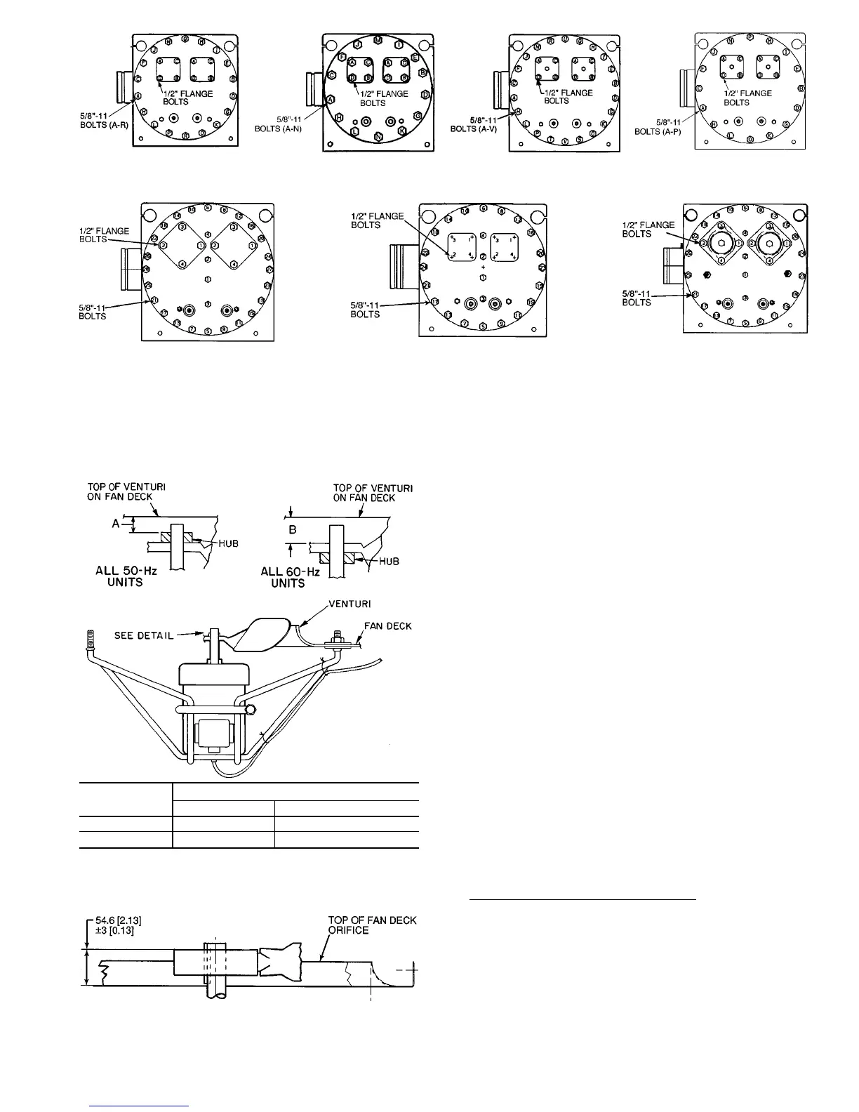
*And associated modular units (see Table 1).
Fig. 26 — Cooler Head Bolt Tightening Sequence
(Typical Tube Sheet)
SIZES 130,150* SIZES 170,190* SIZE 210*
SIZES 080,090* WITH
18-BOLT HEADS
SIZES 080,090* WITH
14-BOLT HEADS
SIZES 100,110* WITH
22-BOLT HEADS
SIZES 100,110* WITH
16-BOLT HEADS
DIMENSION
FAN TYPE
Standard Low-Noise (Optional)
A 0.509 (13 mm) 1.509 (38 mm)
B 0.889 (22 mm) 1.139 (29 mm)
NOTE: Fan rotation is clockwise as viewed from top of unit.
Fig. 27 — Condenser Fan Adjustment
NOTE: Dimensions are in millimeters. Dimensions in [ ] are in inches.
Fig. 28 — Condenser Fan Adjustment,
Units with High Static Fan Option
61
 Loading...