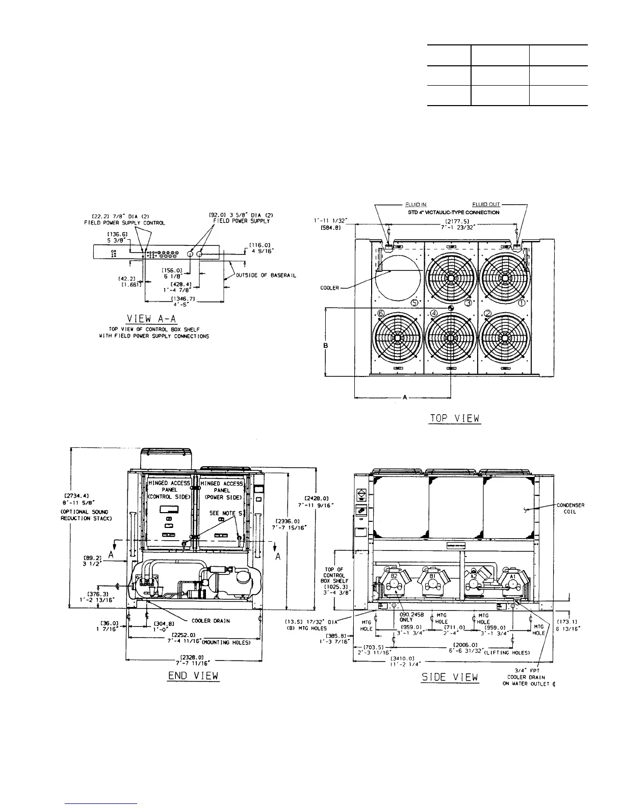
NOTES:
1. Unit must have clearances for airflow (from solid sur-
faces) as follows:
Top — Do not restrict in any way
Ends—5ft[1524 mm]
Sides—6ft[1829 mm]
2. Mounting holes may be used to mount unit to con-
crete pad. They are not recommended for spring iso-
lator location.
3. If spring isolators are used, a perimeter support
channel between the unit and the isolators is
recommended.
4. Dimensions in [ ] are in millimeters.
5. Thru-the-door handles for non-fused disconnect op-
tion on 380/415 v and 460 v units only. When unit
has non-fused disconnect option, power-side door
opens from right side, NOT left side as shown for
standard units.
Fig. 1 — Dimensions; 30GT080,090,230B,245B
CENTER OF GRAVITY
(ft-in.)
30GT
SIZE
080,230B 090,245B
A
5-9
5
⁄
8
[1769]
5-7
5
⁄
16
[1710]
B
3-6
[1067]
3-2
3
⁄
4
[984]
3
 Loading...