37
9.3.1 - Evaporator ow switch and chilled water pump
interlock
NOTE: This is obligatory and 30HXC units:
• The unit water ow switch must be energised.
• The chilled water pump start-up interlock must be
connected.
Failure to follow this instruction will void the Carrier guarantee.
The ow switch is supplied, installed on the evaporator entering
water pipe and preset at the factory to cut out when there is
insufcient water ow.
If any adjustment is required, please refer to chapters:
• 9.3.1.1 for the more recent ow switches,
• 9.3.1.2 for older ow switches (orange colour).
9.3.1.1 - Flow switch - reference number 00PPG000472900A
IMPORTANT: To adjust the setpoint the unit must be energised,
but without water ow.
The default control point is 60 cm/s (0.6 m/s) for all applications.
For option 6 the factory setting is 10 cm/s (0.1 m/s).
Changing the setpoint is only necessary if glycol is used in the
water system (positive brine), and the correct value is 10 cm/s
(0.1 m/s).
If adjustment is required, the push button below must always be
used for safe adjustment. This is available from the Carrier
spare parts department.
• Switch on the unit without water ow.
• Disconnect the ow switch connector and insert the push
button in series with the ow switch.
• Follow sequence A to F below.
NOTE: The new setpoint (in cm/s) corresponds to the duration
(in seconds) the push button is pressed.
A Pressthepushbuttonforlongerthan1second
Releasethebuttonforbetween1and5
seconds
Pressforthenumberofsecondsthatcorrespondsto
the required setpoint (pressing for 10 seconds sets the setpoint to 10 cm/s
or0.1m/s)
Release for 5 seconds
E Thelightisonforthenumberofseconds
thatcorrespondstothesetpoint.
F Theowswitchgoesoutfor5secondsandcanthen
bedisconnectedfromthepushbutton.
A E F
> 1 1 to 5 3to67 5 5 to 65 5
Do not forget to remove the push button at the end of the operation
and replace the connector on the ow switch.
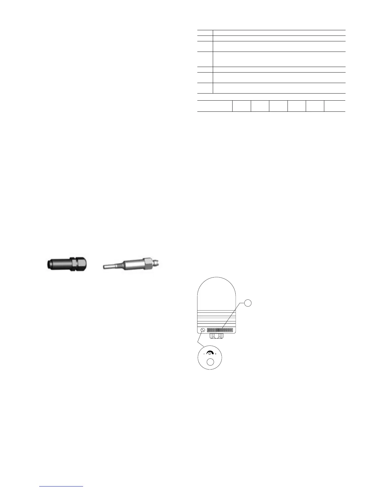
9.3.1.2 - Flow switch - ref. No. HR12AA009EE (orange colour)
If adjustment is necessary:
1. Switch on the unit. Set it to constant ow (preset value).The
yellow LED is illuminated, and the output is switched for
approximately 20 seconds (power-on delay time).
2. Turn the potentiometer until only one green LED is
illuminated. The further the green LED is from the yellow
LED, the safer the adjustment (standby capacity in case of
ow or temperature uctuations).
3. After the adjustment attach the label supplied to the
potentiometer, in order to protect it against unauthorised
tampering.
Terminals 34 and 35 are provided for eld installation of the
chilled water pump interlock (auxiliary contact for pump operation
to be wired on site).
1 Setting potentiometer sensitivity
2 ChainofLEDs
-redLEDlights:theunitisnotadjusted
-yellowLEDlights:theoutputisswitched
-greenLEDlights:theunitisadjusted

 Loading...
