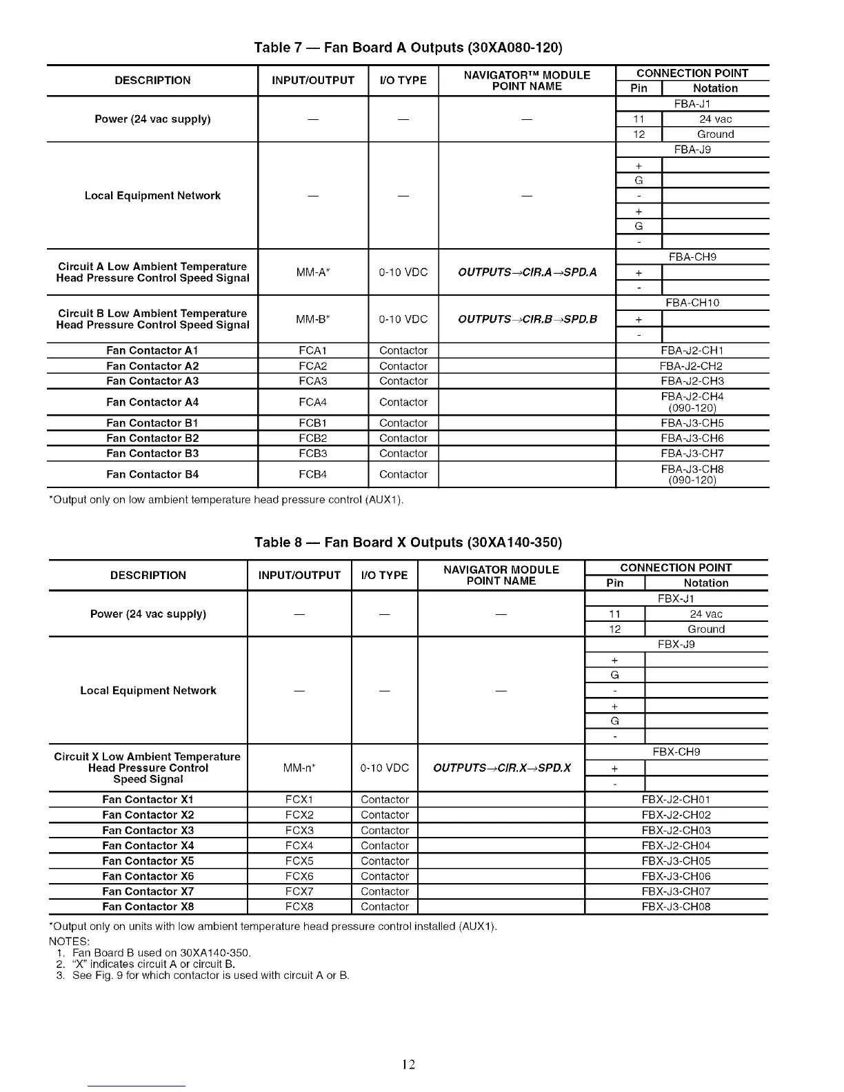
DESCRIPTION
Power (24 vac supply)
Local Equipment Network
Circuit A Low Ambient Temperature
Head Pressure Control Speed Signal
Circuit B Low Ambient Temperature
Head Pressure Control Speed Signal
Fan Contactor A1
Fan Contactor A2
Fan Contactor A3
Fan Contactor A4
Fan Contactor B1
Fan Contactor B2
Fan Contactor B3
Fan Contactor B4
Table 7 -- Fan Board A Outputs (30XA080-120)
INPUT/OUTPUT I/O TYPE NAVIGATOR TM MODULE
POINT NAME
OUTPUTS-_CIR.A -_SPD.A
OUTPUTS_CIR.B _SPD.B
m m
m m
MM-A* 0-10 VDC
MM-B* 0-10 VDC
FCA1 Contactor
FCA2 Contactor
FCA3 Contactor
FCA4 Contactor
FCB 1 Contactor
FCB2 Contactor
FCB3 Contactor
FCB4 Contactor
CONNECTION POINT
Pin J Notation
FBA-J1
11 I 24 vac
12 I Ground
FBA-J9
*Output only on low ambient temperature head pressure control (AUX1).
Table 8 -- Fan Board X Outputs (30XA140-350)
FBA-CH9
I
FBA-CH10
I
FBA-J2-CH 1
FBA-J2-CH2
FBA-J2-CH3
FBA-J2-CH4
(090-120)
FBA-J3-CH5
FBA-J3-CH6
FBA-J3-CH7
FBA-J3-CH8
(090-120)
DESCRIPTION
Power (24 vac supply)
Local Equipment Network
Circuit X Low Ambient Temperature
Head Pressure Control
Speed Signal
Fan Contactor X1
Fan Contactor X2
Fan Contactor X3
Fan Contactor X4
Fan Contactor X5
Fan Contactor X6
Fan Contactor X7
Fan Contactor X8
INPUT/OUTPUT
MMm*
I/O TYPE
0-10 VDC
NAVIGATOR MODULE
POINT NAME
OUTPUTS_CIR.X_SPD.X
CONNECTION POINT
Pin Notation
FBX-J1
11 24 vac
12 Ground
FBX-J9
+
G
+
G
FBX-CH9
+
FCX1 Contactor FBX-J2-CH01
FCX2 Contactor FBX-J2-CH02
FCX3 Contactor FBX-J2-CH03
FCX4 Contactor FBX-J2-CH04
FCX5 Contactor FBX-J3-CH05
FCX6 Contactor FBX-J3-CH06
FCX7 Contactor FBX-J3-CH07
FCX8 Contactor FBX-J3-CH08
*Output only on units with low ambient temperature head pressure control installed (AUX1).
NOTES:
1. Fan Board B used on 30XA140-350.
2. "X" indicates circuit A or circuit B.
3. See Fig. 9 for which contactor is used with circuit A or B.
12
 Loading...


