CAPACITY CONTROL OVERRIDES (Run Status-+
VIEW _CAP.S) -- The following ovemdes will modify the
norlnal operation routine. If any of the following override con-
ditions listed below is satisfied, it shall determine the capacity
change instead of the normal control. Overrides are listed by
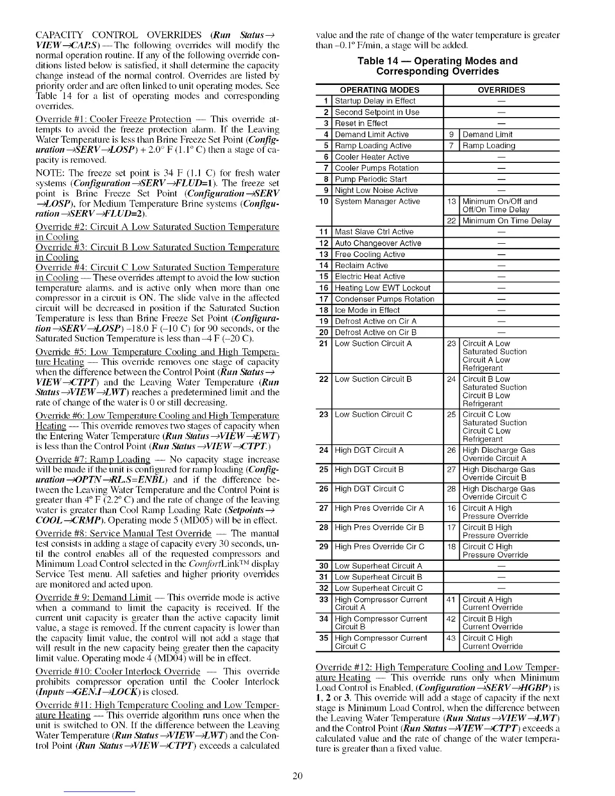
priority order and ale often linked to unit operating modes. See
Table 14 for a list of operating modes and corresponding
overrides.
Override #1 : Cooler Freeze Protection -- This ovemde at-
tempts to avoid the freeze protection alarm. If the Leaving
Water Tempelature is less than Brine Freeze Set Point (Config-
uration--¢SERV--cLOSP) + 2.0 ° F (1.1 ° C) then a stage of ca-
pacity is removed.
NOTE: The freeze set point is 34 F (1.1 C) for fresh water
systems (Configuration ---_ERV---)FLUD=I). The freeze set
point is Brine Freeze Set Point (Configuration--_S'ERV
--_LOSP), for Medium Temperature Brine systems (Configu-
ration ---_S'ERV--)FLUD=2 ).
Override #2: Circuit A Low Saturated Suction Temperature
in Cooling
Override #3: Circuit B Low Saturated Suction Temperature
in Cooling
Override #4: Circuit C Low Saturated Suction Temperature
in Cooling -- These overrides attempt to avoid the low suction
temperatme alarlns, and is active only when more than one
compressor in a circuit is ON. The slide valve in the affected
circuit will be decreased in position if the Saturated Suction
Temperature is less than Brine Freeze Set Point (Configura-
tion--+SERV--+LOSP) -18.0 F (-10 C) for 90 seconds, or the
Saturated Suction Temperature is less than -4 F (-20 C).
Override #5: Ix_w Temperature Cooling and High Tempera-
ture Heating -- This ovenide removes one stage of capacity
when the difference between the Control Point (Run Status--)
VIEW_CTPT) and the Leaving Water Temperature (Run
Status--+VIEW--+LWT) reaches a predetermined limit and the
rate of change of the water is 0 or still decreasing.
Override #6: Ix_w Temperature Cooling and High Temperatme
Heating -- This ovenide lemoves two stages of capacity when
the Entering Water Temperature (Run Status--+VIEW--+EWT)
is less than the Control Point (Run Status--+VIEW_CTPT.)
Override #7: Ramp Loading -- No capacity stage increase
will be made if the unit is configured for ramp loading (Cottfig-
uration--)OPTN--)RL.S=ENBL) and if the diffelence be-
tween the Leaving Water Temperatme trod the Control Point is
gleater than 4° F (2.2 ° C) and the rate of change of the leaving
water is greater than Cool Rmnp Ix_ading Rate (Se&oints-e
COOL_CRMP). Operating mode 5 (MD05) will be in effect.
Override #8: Service Manual Test Override -- The manu:d
test consists in adding a stage of capacity eve U 30 seconds, un-
til the control enables all of the requested compressors and
Minimum Ix_ad Control selected in the Crml/brtLink TM display
Service Test menu. All safeties and higher priority overrides
ale monitored and acted upon.
Override # 9: Demand Limit -- This override mode is ttctive
when a command to limit the capacity is received. If the
current unit capacity is gleater than the active capacity limit
v:due, a stage is removed. If the current capacity is lower than
the capacity limit value, the control will not add a stage that
will result in the new capacity being gleater then the capacity
limit v_due. Operating mode 4 (MD04) will be in effect.
Override #10: Cooler Interlock Override -- This override
prohibits compressor operation until the Cooler Interlock
(hlputs _GEN.I---_LOCK) is closed.
Override #11 : High Temperature Cooling and Low Temper-
ature Heating -- This override algorithm runs once when the
unit is switched to ON. If the difference between the Leaving
Water Temperatme (Run Status --+VIEW--+LWT) and the Con-
trol Point (Run Status---_VIEW_42TPT) exceeds a c:dculated
value and the rate of change of the water temperatureis greater
than -0.1 ° F/rain, a stage will be added.
Table 14 -- Operating Modes and
Corresponding Overrides
1
2
3
4
5
6
7
8
9
10
11
12
13
14
15
16
17
18
19
20
21
22
23
24
25
26
27
28
29
3O
31
32
33
34
35
OPERATING MODES
Startup Delay in Effect
Second Setpoint in Use
Reset in Effect
Demand Limit Active
Ramp Loading Active
Cooler Heater Active
Cooler Pumps Rotation
Pump Periodic Start
Night Low Noise Active
System Manager Active
Mast Slave Ctrl Active
Auto Changeover Active
Free Cooling Active
Reclaim Active
Electric Heat Active
Heating Low EWT Lockout
Condenser Pumps Rotation
Ice Mode in Effect
Defrost Active on Cir A
Defrost Active on Cir B
Low Suction Circuit A
Low Suction Circuit B
Low Suction Circuit C
High DGT Circuit A
High DGT Circuit B
High DGT Circuit C
High Pres Override Cir A
High Pres Override Cir B
High Pres Override Cir C
Low Superheat Circuit A
Low Superheat Circuit B
Low Superheat Circuit C
High Compressor Current
Circuit A
High Compressor Current
Circuit B
High Compressor Current
Circuit C
OVERRIDES
9 Demand Limit
7 Ramp Loadng
13 Minimum On/Off and
Off/On Time Delay
22 Minimum On Time Delay
m
m
m
m
m
23 Circuit A Low
SaturatedSuction
Circuit A Low
Refrigerant
24 Circuit B Low
SaturatedSuction
Circuit B Low
Refrigerant
25 Circuit C Low
SaturatedSuction
Circuit C Low
Refrigerant
26 High Discharge Gas
Override Circuit A
27 High Discharge Gas
Override Circuit B
28 High Discharge Gas
Override Circuit C
16 Circuit A High
Pressure Override
17 Circuit B High
Pressure Override
18 Circuit C High
Pressure Override
41 Circuit A High
Current Override
42 Circuit B High
Current Override
43 Circuit C High
Current Override
Override #12: High Temperature Cooling and Low Temper-
ature Heating -- This override runs only when Minimum
Load Control is Enabled, (Configuration ---)SERV--cHGBP) is
1, 2 or 3. This ovenide will add a stage of capacity if the next
stage is Minimum Load Control, when the difference between
the Leaving Water Temperature (Run Status---)VIEW---)LWT)
and the Control Point (Run Status --+VIEW_CTPT) exceeds a
calculated value and the rate of change of the water tempera-
ture is greater than a fixed value.
20