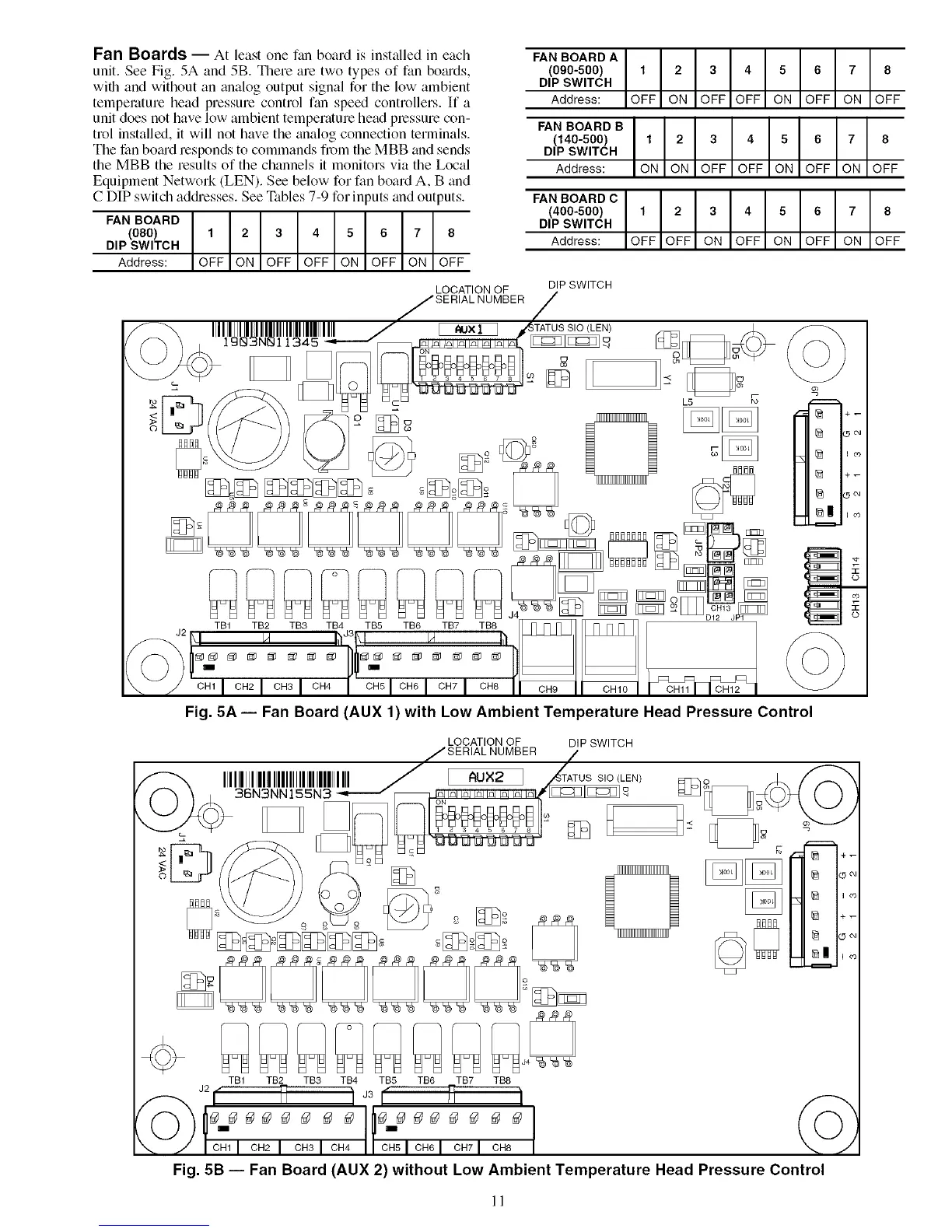
Fan Boards -- At least one f;m board is installed in each
unit. See Fig. 5A and 5B. There are two types of fan bomds,
with and without an analog output signal for the low ambient
temperature head pressure control fan speed controllers. If a
unit does not have low ambient temperature head pressure con-
trol installed, it will not have the analog connection terminals.
The fan bo;ud responds to commands from the MBB and sends
the MBB the results of the channels it monitors via the Local
Equipment Network (LEN). See below for fan board A, B and
C DIP switch addresses. See Tables 7-9 for inputs and outputs.
FAN BOARD
(080) 1 2 3 4 5 6 7 8
DIP SWITCH
Address: OFF ON OFF OFF ON OFF ON OFF
FAN BOARD A
(090-500) 1 2
DIP SWITCH
Address: OFF ON
3 4 5 6 7 8
OFF OFF ON OFF ON OFF
FAN BOARD B
(140-500) 1 2
DIP SWITCH
Address: ON ON
3 4 5 6 7 8
OFF OFF ON OFF ON OFF
FAN BOARD C
(400-500) 1 2
DIP SWITCH
Address: OFF OFF
3 4 5 6 7 8
ON OFF ON OFF ON OFF
LOCATION OF DIP SWITCH
JSERIALNUMBER /
IIIIIIIIIIIIIIIIIIIIIIIIIIIIIIIIIIII.../7 _ _]TATUS SIC (LE_ _ _..
IgN3NNl1345 _ _ [__ [_JFr_d@)
c _ C
TB1 TB2 TB3 TB4 TB5 TB6 TB7 TB8
J2 I/I
I®
I_
I+-
I®
Fig. 5A- Fan Board (AUX 1)with Low Ambient Temperature Head Pressure Control
LOCATION OF DIP SWITCH
cccccc Q
TB1 TB2 TB3 TB4 TB5 TB6 TB7 TB8
/ cn_I cn_ I CH_I CH4I/ CHaI CH_I CHVI CHS I
Fig. 5B -- Fan Board (AUX 2) without Low Ambient Temperature Head Pressure Control
11
 Loading...


