START-UP
Do not manu_dly operate contactors. Serious damage to the
machine may result.
Actual Start-Up- Actual start-_q) should be done only
under Sul)eia'ision o/ a quali/ied r@'igerution Wchniciun.
1. Be sure all oil, discharge, suction service valves (if
equipped) and liquid line service valves are open.
2. Using the Navigato( r_'rdisplay, set leaving-fluid set point
(Set PoOlt_COOL_4JSP.I). No cooling range adjust-
ment is necess_uy.
3. If optional control functions or accessories _ue being
used, the unit must be properly configured. Refer to
Configuration Options section for details.
4. Complete the Start-Up Checklist to verily all components
ale operating properly.
5. Turn Enable/Off/Remote contact switch to Enable position.
6. Allow unit to operate and confirm that everything is
functioning properly. Check to see that leaving fluid
temperature aglees with leaving set point Control Point
(Run Status ---)VIEW_4JTPT).
Operating Limitations
TEMPERATURES- Unit operating temperature limits are
listed in Table 27.
Table 27 -- Temperature Limits for Standard Units
TEMPERATURE 1F5 CMaximum Ambient Temperature 52
Minimum Ambient Temperature 32 0
Maximum Cooler EWT* _095 35
Maximum Cooler LWT 60 15
Minimum Cooler LWTt 4.4
LEGEND
EWT -- Entering Fluid (Water) Temperature
LWT -- Leaving Fluid (Water) Temperature
*For sustained operation, EWT should not exceed 85 F (29.4 C).
1-Unit requires brine modification for operation below this
temperature.
Low Ambient Temperature Operation -- If unit operating
temperatures below 32 F (0 ° C) are expected, refer to separate
unit installation instructions for low ambient temperature oper-
ation using accessory low ambient temperature head pressure
control, if not equipped. Contact your C_urier representative for
details.
NOTE: If wind velocity is expected to be greater than 5 mph
(8 kin/h) wind baffles and brackets must be field-fabricated
and installed for all units using accessory low ambient head
pressure control. See the 30XA Installation Instructions or the
low ambient temperature head pressure control accessory
installation instructions for more information.
Brine duty application (below 40 F [4.4 C] LCWT) for
chiller normally requires factory modification. Contact a
Canier Representative for details regarding specific
applications. Operation below 40 F (4.4 C) LCWT with-
out modification can result in compressor failure.
VOLTAGE
Muin Power Supply -- Minimum and maximum acceptable
supply voltages are listed in the Inst_dlation Instructions.
Unbalanced 3-Phase Supply Voltuge -- Never operate a motor
where a phase imb_dance between phases is greater than 2%.
To determine percent voltage imb_dance:
max voltage deviation from
avg voltage
% Voltage Imbalance = 100 x
average voltage
The maximum voltage deviation is the largest difference
between a voltage measurement across 2 legs and the average
across _dl 3 legs.
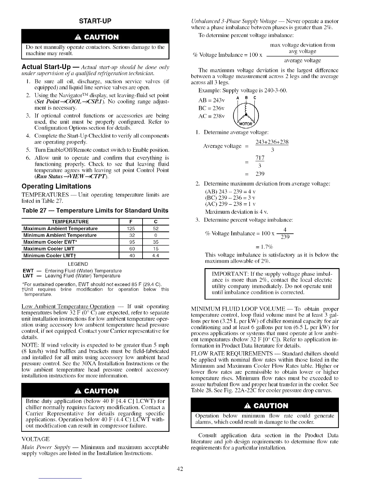
Example: Supply voltage is 240-3-60.
AB = 243v A B C
BC = 236v K I "_
AC = 238v
1. Determine average voltage:
Average voltage =
m
z
243+236+238
3
717
3
239
2. Determine maximum deviation from average voltage:
(AB) 243 - 239 = 4 v
(BC) 239 - 236 = 3 v
(AC) 239 - 238 = 1 v
Maximum deviation is 4 v.
3. Determine percent voltage imbalance:
4
% Voltage hnbalance = 100 x 23----7
= 1.7%
This voltage imbalance is satisfactory as it is below the
maximum allowable of 2%.
IMPORTANT: If the supply voltage phase imbal-
ance is more than 2%, contact the local electric
utility company immediately. Do not operate unit
until imbalance condition is corrected.
MINIMUM FLUID LOOP VOLUME -- To obtain proper
temperature control, loop fluid volume must be at least 3 gal-
lons per ton (3.25 L per kW) of chiller nominal capacity for air
conditioning and at least 6 gallons per ton (6.5 L per kW) for
process applications or systems that must operate at low ambi-
ent temperatures (below 32 F [0 ° C]). Refer to application in-
formation in Product Data literature for details.
FLOW RATE REQUIREMENTS -- Standard chillers should
be applied with nominal flow rates within those listed in the
Minimum and Maximum Cooler Flow Rates table. Higher or
lower flow rates are permissible to obtain lower or higher
temperature rises. Minimum flow rates must be exceeded to
assure turbulent flow and proper heat transfer in the coolel: See
Table 28. See Fig. 22A-22C for cooler pressure drop curves.
Operation below minimum flow rate could generate
alarms, which could result in &_mage to the coolel:
Consult application &_ta section in the Product Data
literature and job design requirements to determine flow rate
requirements for a particular inst:dlation.
42
 Loading...


