RUN
STATUS
Auto Display
(VIEW)
Remote
User Interface
(R.CCN)
Machine
Starts/Hours
(RUN)
Compressor
Run Hours
(HOUR)
Compressor
Starts
(STRT)
Fan Run
Hours
(FAN)
Compressor
Disable
(CRUN)
Predictive
Maintenance
(MAIN)
Software Versions
(VERS)
Table 1 -- ComfortLink TM Display Menu Structure
SERVICE TEMPERATURES
TEST
Manual Unit
Test Mode Temperatures
(TEST) (UNIT)
Quick Circuit A
Test Mode Temperatures
(QUIC) (CIR,A)
Circuit B
Temperatures
(CIR,B)
Circuit C
Temperatures
(CIR.C)
MODE
SET INPUTS OUTPUTS CONFIGURATION
PRESSURES POINTS
Circuit A Cooling General Circuit A Display
Pressures Setpoints Inputs Outputs Configuration
(PRC.A) (COOL) (GEM,I) (CIR.A) (DISP)
Circuit B Heating Circuit B Unit
Pressures Setpoints Outputs Configuration
(PRC.B) (HEAT) (CIR.B) (UNIT)
Circuit C Misc. Circuit C Service
Pressures Setpoints Outputs Configurations
(PRC,C) (MISC) (CIR,C) (SERV)
General Options
Outputs Configuration
(GEM.O) (OPTN)
Reset,
Demand Limit,
Master/Slave
(RSET)
TIME
CLOCK
Time of Day
(TIME)
Day, Date
(DATE)
Schedule 1
(SCH1)
Schedule 2
(SCH2)
Holidays
(HOLI)
Service
Maintenance
Configuration
(MCFG)
OPERATING
MODES
Operating
Control Type
(SLCT)
Operating
Modes
(MODE)
ALARMS
Reset Current
Alarms
(R.ALM)
Current
Alarms
(ALRM)
Alarm
History
(H.ALM)
CONTROLS
General -- The 30XA air-cooled liquid chillers contain the
Con_fbrtLink TM electronic control system that controls and
monitors all operations of the chillel: The control system is
composed of several components as listed in the following sec-
tions. All machines have at the ve U least a Main Base Board
(MBB), Navigatoi r_'_module, electronic expansion valve board
(EXV), fan board, Compressor Protection board, Emergency
On/Off switch, an Enable-Off- Remote Contact switch.
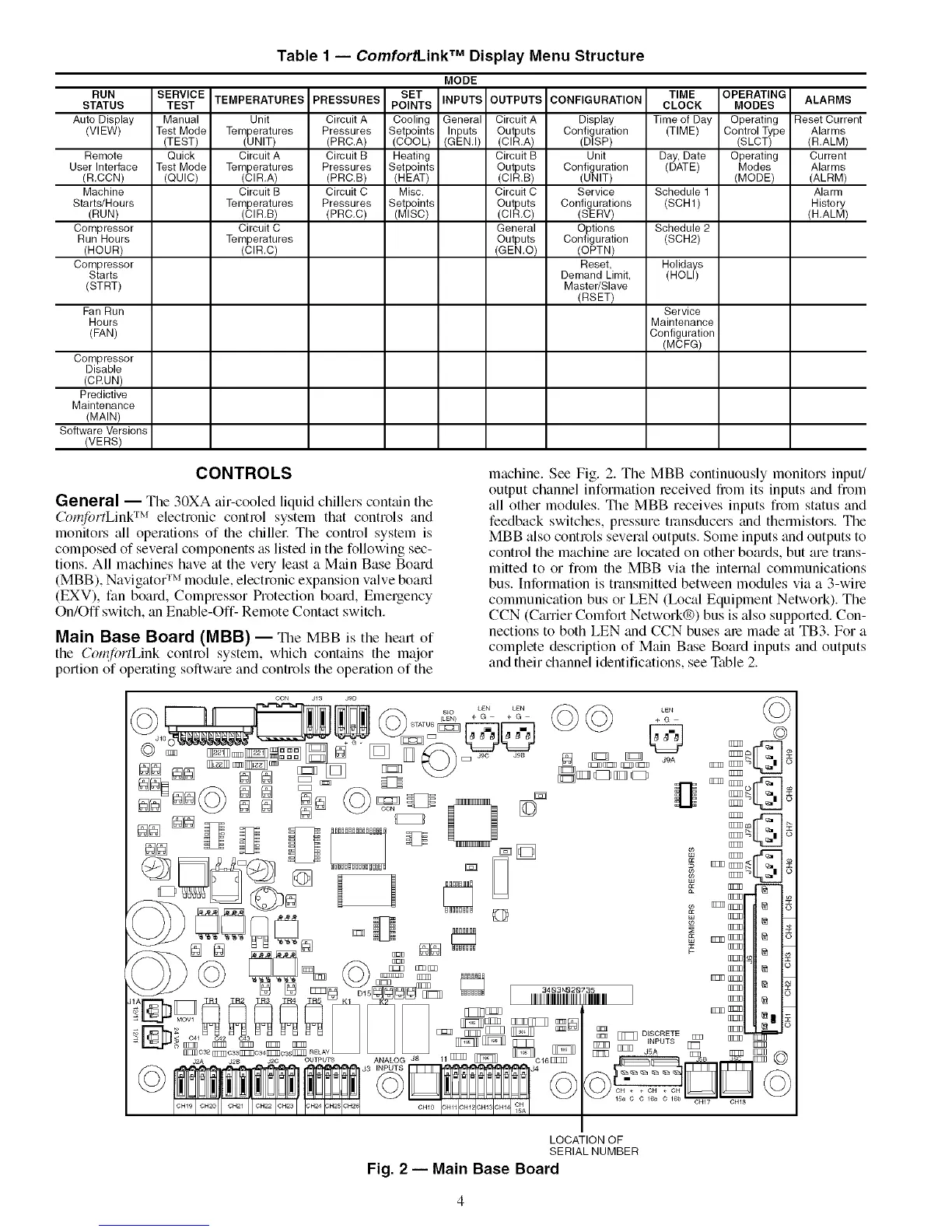
Main Base Board (MBB) -- Tile MBB is tile heart of
the Corqi0rtLink control system, which contains the major
portion of operating softwme and controls the operation of the
machine. See Fig. 2. The MBB continuously monitors input!
output channel information received from its inputs and from
all other modules. The MBB receives inputs from status and
feedback switches, pressure transducers and thermistors. The
MBB also controls several outputs. Some inputs and outputs to
control the machine me located on other bo_uds, but are trans-
mitted to or from the MBB via the internal communications
bus. Information is transmitted between modules via a 3-wire
communication bus or LEN (Ix)cal Equipment Network). The
CCN (Carrier Comfort Network®) bus is also supported. Con-
nections to both LEN and CCN buses are made at TB3. For a
complete description of Main Base Board inputs and outputs
and their channel identifications, see Table 2.
LOCATION OF
SERIAL NUMBER
Fig. 2 -- Main Base Board

 Loading...


