©
INPUT
4-20 mA Demand Limit
4-20 mA Temperature
Reset]Cooling Setpoint
Demand Limit SW2
Ice Done
Occupancy Override
Remote Lockout Switch
SPT
OUTPUT
% Total Capacity
RUN R
SHD R
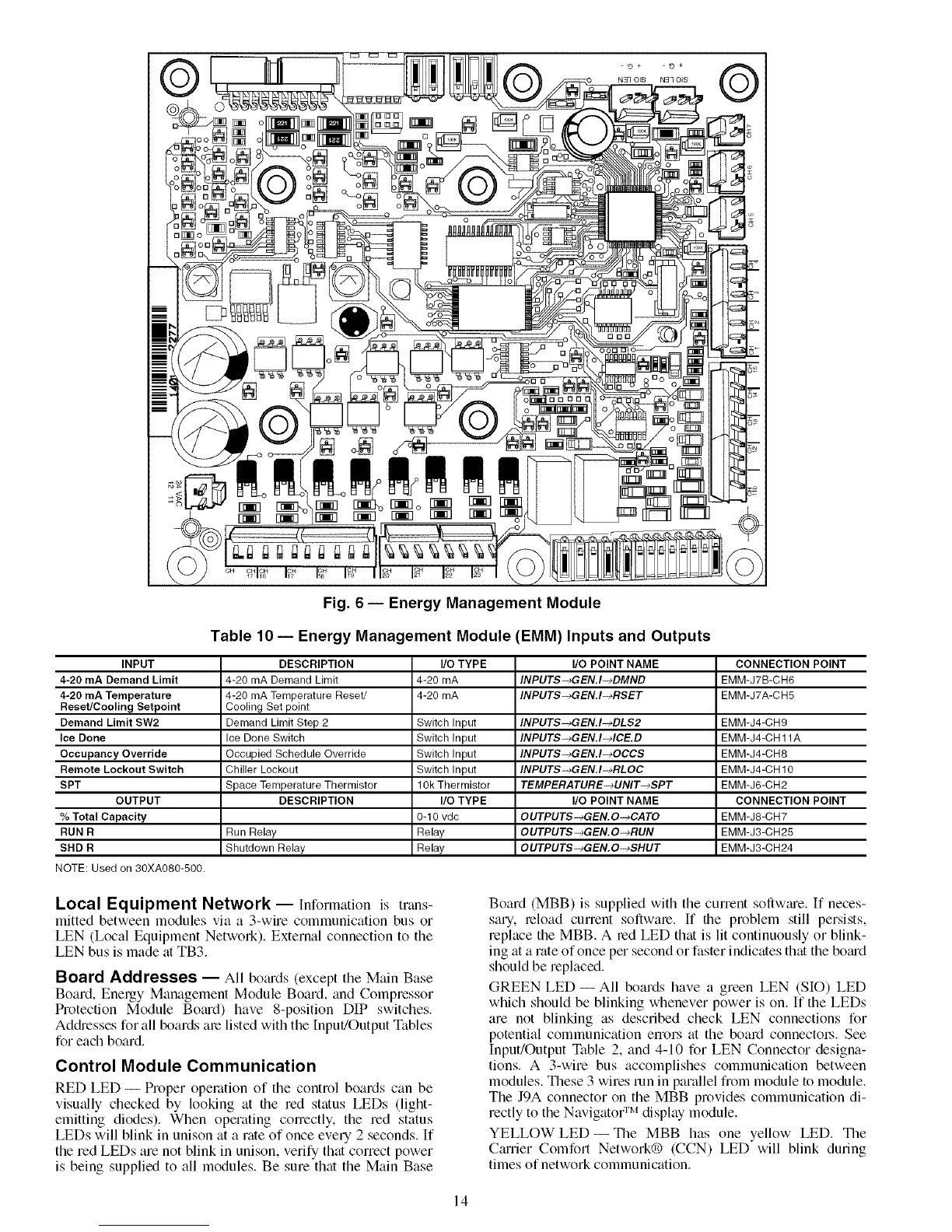
NOTE: Used on 30XA080-500.
Fig. 6 -- Energy Management Module
Table 10 -- Energy Management Module (EMM) Inputs and Outputs
DESCRIPTION I/O TYPE I/O POINT NAME CONNECTION POINT
4-20 mA Demand Limit 4-20 mA INPUTS-_GEN.I-_DMND EMM-J7B-CH6
4-20 mA Temperature Reset/ 4-20 mA INPUT$-_GEN.I-_RSET EMM-J7A-CH5
Cooling Set point
Demand Limit Step 2 Switch Input INPUT$-_GEN.I-_DLS2 EMM-J4-CH9
Ice Done Switch Switch Input INPUTS-_GEN.I-MCE.D EMM-J4-CH 11A
Occupied Schedule Override Switch Input INPUTS-_GEN.I-_OCCS EMM-J4-CH8
Chiller Lockout Switch Input INPUT$-_GEN.I-_RLOC EMM-J4-CH 10
Space Temperature Thermistor 10k Thermistor TEMPERATURE-_UNIT-_$PT EMM-J6-CH2
DESCRIPTION I/O TYPE I/O POINT NAME CONNECTION POINT
0-10 vdc OUTPUTS-+GEN.O-+CATO EMM-J8-CH7
Run Relay Relay OUTPUT$-_GEN.O-_RUN EMM-J3-CH25
Shutdown Relay Relay OUTPUTS-_GEN.O-_SHUT EMM-J3-CH24
Local Equipment Network --Information is trans-
mitted between modules via a 3-wire cornmunication bus or
LEN (Local Equipment Network). External connection to the
LEN bus is made fit TB3.
Board Addresses -- All bofu'ds (except the Main Base
Board, Energy Management Module Board, find Compressor
Protection Module Bornd) have 8-position DIP switches.
Addresses for all boards ate listed with the Input!Output Tables
for each board,
Control Module Communication
RED LED -- Proper operation of the control boards can be
visually checked by looking at file red status LEDs (ligltt-
emitting diodes). When operating correctly, the red status
LEDs will blink in unison at a rate of once every 2 seconds. If
the red LEDs are not blink in unison, verify that correct power
is being supplied to all modules. Be sure that the Main Base
Board (MBB) is supplied with the cunent soflwme. If neces-
sary, teload current soflwate. If tlte problem still persists,
replace the MBB. A red LED that is lit continuously or blink-
ing at a rate of once per second or faster indicates that the bomd
should be replaced.
GREEN LED -- All boards have a green LEN (SIO) LED
which should be blinking whenever power is on. If the LEDs
are not blinking as described check LEN connections for
potential communication errors fit the board connectot_. See
Input/Output Table 2, and 4-10 for LEN Connector designa-
tions. A 3-wire bus accomplishes communication between
modules. These 3 wires tun in parallel from module to module.
The J9A connector on the MBB provides communication di-
rectly to the Navigator :m display module.
YELLOW LED- Tlte MBB has one yellow LED. The
Cmtier Comfort Network® (CCN) LED will blink during
times of network communication.
14

 Loading...


