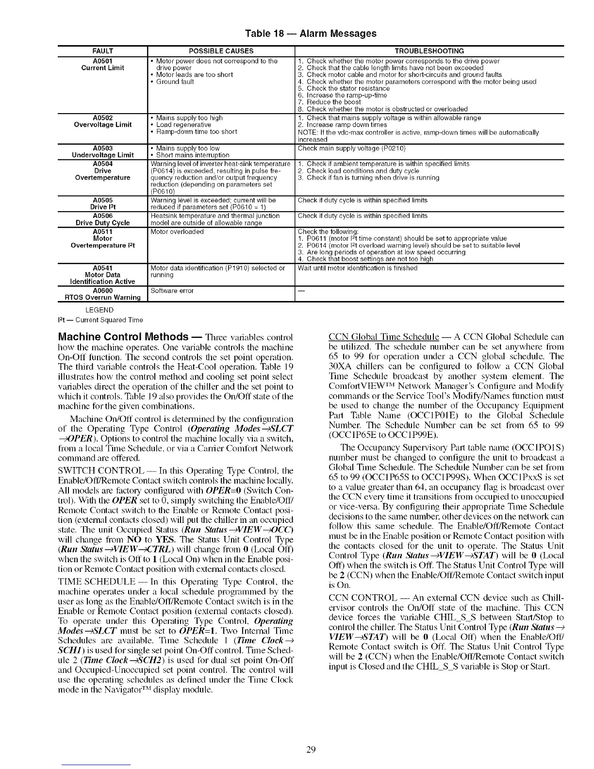
Table 18- Alarm Messages
FAULT
A0501
Current Limit
A0502
Overvoltage Limit
POSSIBLE CAUSES
• Motor power does not correspond to the
drive power
• Motor leads are too short
• Ground fault
• Mains supply too high
• Load regenerative
• Ramp-down time tee short
A0503 • Mains supply too low
Undervoltage Limit • Short mains interruption
A0504 Warning level of inverter heat-sink temperature 1. Check if ambient temperature is within specified limits
Drive (P0614) is exceeded, resulting in pulse fre- 2. Check load conditions and duty cycle
Overtemperature quency reduction and/or output frequency 3. Check iffan is turning when drive is running
reduction (depending on parameters set
(P0610)
A0505 Warning level is exceeded; current will be Check if duty cycle is within specified limits
Drive 12t reduced if parameters set (P0610 = 1)
A0506 Heatsink temperature and thermal junction Check if duty cycle is within specified limits
Drive Duty Cycle model are outside of allowable range
A0511 Motor overloaded Check the following:
Motor 1. P0611 (motor 12ttime constant) should be set to appropriate value
Overtemperature 12t 2. P0614 (motor 12toverload warning level) should be set to suitable level
3. Are long periods of operation at low speed occurring
4. Check that boost settings are not too high
A0541 Motor data identification (P1910) selected or Wait until motor identification is finished
Motor Data running
Identification Active
A0600 Software error
RTOS Overrun Warnin_
LEGEND
i2t -- Current Squared Time
TROUBLESHOOTING
1. Check whether the motor power corresponds to the drive power
2. Check that the cable length limits have not been exceeded
3. Check motor cable and motor for short-circuits and ground faults
4. Check whether the motor parameters correspond with the motor being used
5. Check the stator resistance
6. Increase the ramp-up-time
7. Reduce the boost
8. Check whether the motor is obstructed or overloaded
1. Check that mains supply voltage is within allowable range
2. Increase ramp down times
NOTE: If the vdc-max controller is active, ramp-down times will be automatically
increased
Check main supply voltage (P0210)
Machine Control Methods -- Tinge variables control
how the machine operates. One vmiable controls the machine
On-Off function. The second controls the set point operation.
The third variable controls the Heat-Cool operation. Table 19
illustrates how the control method and cooling set point select
variables dilect file operation of the chiller and the set point to
which it controls. Table 19 _flso provides the On/Off state of the
machine for the given combinations.
Machine On/Off control is determined by the configuration
of the Operating Type Control (Operating Modes--+SLCT
_OPER). Options to control the machine locally via a switch,
from a local Time Schedule, or via a Carrier Comfort Network
command are offered.
SWITCH CONTROL --In this Operating Type Control, the
Enable/Off/Remote Contact switch controls the machine locally.
All models are factory configured with OPER=O (Switch Con-
trol). With the OPER set to 0, simply switching the Enable/Off/
Remote Contact switch to file Enable or Remote Contact posi-
tion (external contacts closed) will put the chiller in tin occupied
state. The unit Occupied Status (Run Status-+VIEW_OCC)
will change fiom NO to YES. The Status Unit Control Type
(Run Status--_VIEW_CTRL) will change fiom 0 (Ix_cal Off)
when the switch is Off to 1 (Ix_cal On) when in the Enable posi-
tion or Remote Contact position with external contacts closed.
TIME SCHEDULE- In this Operating Type Control, the
machine operates under a local schedule programmed by the
user as long as the Enable/Off/Remote Contact switch is in the
Enable or Remote Contact position (external contacts closed).
To operate under this Operating Type Control, Operating
Modes-+SLCT must be set to OPER=I. Two Internal Time
Schedules are available. Time Schedule 1 (Time Clock--_
SCH1) is used for single set point On-Off control. Time Sched-
ule 2 (Time Clock_SCH2) is used for dual set point On-Off
and Occupied-Unoccupied set point control. The control will
use the operating schedules as defined under the Time Clock
mode in the Navigato( r_'_display module.
CCN Global Time Schedule -- A CCN Global Schedule can
be utilized. The schedule number can be set anywhere from
65 to 99 for operation under a CCN glob_d schedule. The
30XA chillers can be configmed to follow a CCN Global
Time Schedule broadcast by another system element. The
IM
ComfortVIEW Network Manager's Configure and Modily
commands or the Selwice Tool's Modify/Nmnes function must
be used to change the number of the Occupancy Equipment
Part Table Name (OCCIP01E) to the Global Schedule
Numbel: The Schedule Number can be set from 65 to 99
(OCC 1P65E to OCC 1P99E).
The Occupancy Supervisory Part table name (OCCIPOI S)
number must be changed to configure the unit to broadcast a
Global Time Schedule. The Schedule Number can be set from
65 to 99 (OCCIP65S to OCCItX)9S). When OCCIPxxS is set
to a v_due greater than 64, an occupancy flag is broadcast over
the CCN every time it transitions from occupied to unoccupied
or vice-versa. By configuring their appropriate Time Schedule
decisions to fl-_esame numbel, other devices on the network can
follow this same schedule. The Enable/Off/Remote Contact
must be in the Enable position or Remote Contact position with
flae contacts closed for the unit to operate. The Status Unit
Control Type (Run Status--cVIEW--cSTAT) will be 0 (Ix_cal
Off) when the switch is Off. The Status Unit Control Type will
be 2 (CCN) when the Enable/Off/Remote Contact switch input
is On.
CCN CONTROL -- An external CCN device such as Chill-
ervisor controls the On/Off state of the machine. This CCN
device forces the variable CHIL_S_S between Start/Stop to
control the chillel: The Status Unit Control Type (Run Status--€
VIEWS'TAT) will be 0 (Loc_d Off) when the Enable/Off/
Remote Contact switch is Off. The Status Unit Control Type
will be 2 (CCN) when the Enable/Off/Remote Contact switch
input is Closed and the CHIL_S_S variable is Stop or Start.
29