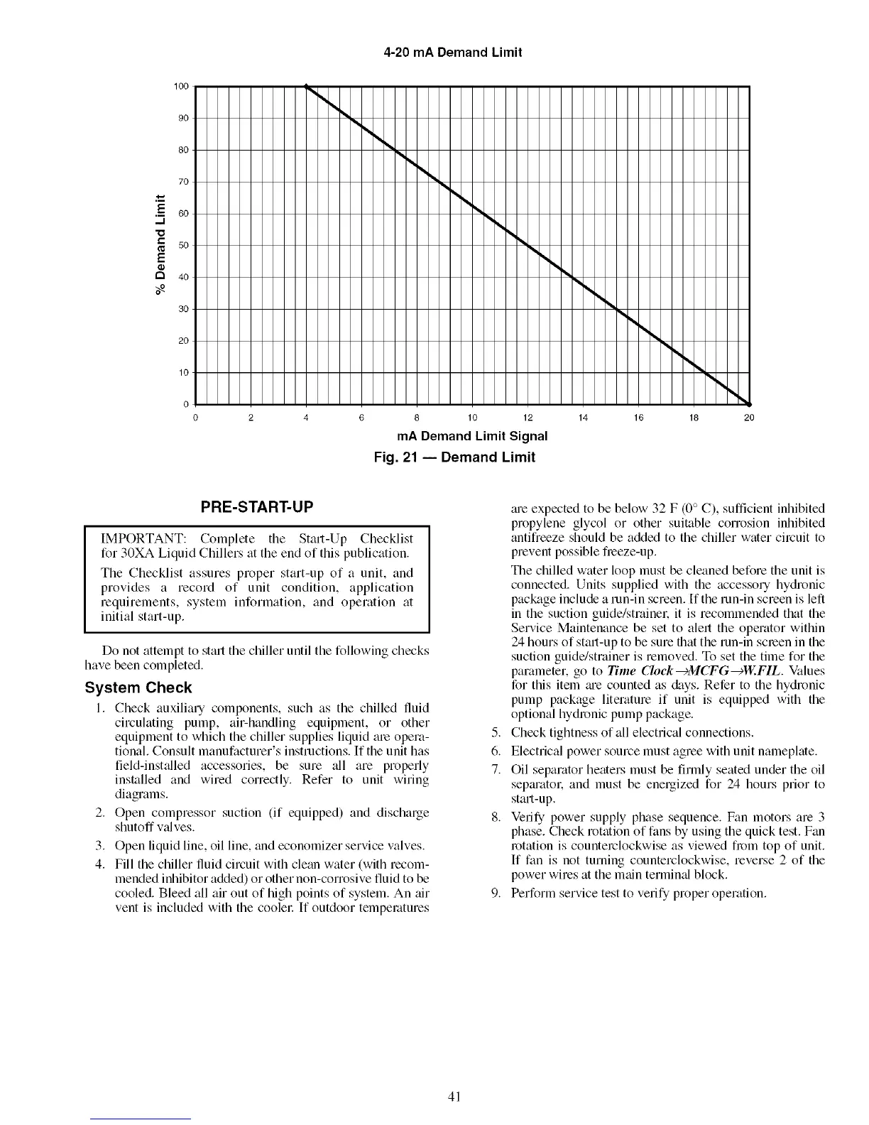
4-20 mA Demand Limit
100
90
80
70
.-_ 60
,,,,,.I
"0
so
E
r"t 40
3O
20
10
I
10 12
mADemand Limit Signal
Fig. 21 -- Demand Limit
14 16 18 2O
PRE-START-UP
IMPORTANT: Complete the Stall-Up Checklist
for 30XA Liquid Chillers at the end of this publication.
The Checklist assures proper start-up of a unit, and
provides a record of unit condition, application
requirements, system information, and operation at
initial start-up.
Do not attempt to start the chiller until the following checks
have been completed.
System Check
I. Check auxiliary components, such as the chilled fluid
circulating pump, air-handling equipment, or other
equipment to which the chiller supplies liquid ale opela-
tional. Consult manufacturer's instructions. If the unit has
field-installed accessories, be sure _11 are properly
installed and wired correctly. Refer to unit wiring
diagrams.
2. Open compressor suction (if equipped) and discharge
shutoff v_dyes.
3. Open liquid line, oil line, and economizer service valves.
4. Fill the chiller fluid circuit with clean water (with recom-
mended inhibitor added) or other non-corrosive fluid to be
cooled. Bleed all air out of high points of system. An air
vent is included with the coolel: If outdoor temperatures
5.
6.
7.
tue expected to be below 32 F (0° C), sufficient inhibited
propylene glycol or other suitable corrosion inhibited
antifreeze should be added to the chiller water circuit to
prevent possible fieeze-up.
The chilled water loop must be cleaned before the unit is
connected. Units supplied with the accessory hydronic
package include a run-in screen. If the run-in screen is left
in the suction guide/strainel: it is recommended that the
Service Maintenance be set to alert the operator within
24 hours of stall-up to be sure that the run-in screen in the
suction guide/strainer is removed. To set the time for the
parameter, go to Time Cloek---)MCFG---)W.FIL. Values
for this item me counted as &tys. Refer to the hydronic
pump package literature if unit is equipped with the
optional hydronic pump package.
Check tightness of all electrical connections.
Electrical power source must agree with unit nameplate.
Oil separator heaters must be firmly seated under the oil
septu'atol: and must be energized for 24 hours prior to
start-up.
Verify power supply phase sequence. Fan motors are 3
phase. Check rotation of fans by using the quick test. Fan
rotation is counterclockwise as viewed from top of unit.
If fan is not turning counterclockwise, reverse 2 of the
power wires at the main terminal block.
Perform service test to verify proper operation.
41
 Loading...


