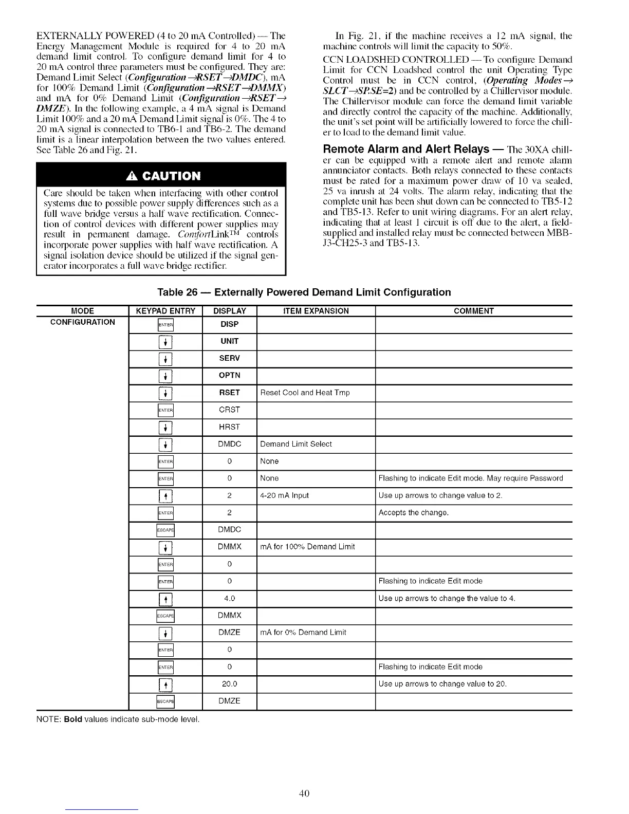
EXTERNALLY POWERED (4 to 20 mA Controlled) -- The
Energy Management Module is required for 4 to 20 mA
demand limit control. To configure demand limit for 4 to
20 mA control three parameters must be configured. They are:
Demand Limit Select (Configuration _RSET--+DMDC), mA
for 100% Demand Limit (Configuration---)RSET-cDMMX)
and mA for 0% Demand Limit (Configuration---)RSET---)
DMZE). In the following example, a 4 mA sigmd is Demand
Limit 100% and a 20 mA Demand Limit signal is 0%. The 4 to
20 mA signal is connected to TB6-1 and TB6-2. The demand
limit is a linear intelpolation between the two values entered.
See Table 26 and Fig. 21.
Ctue should be taken when interfacing with other control
systems due to possible power supply differences such as a
full wave bridge versus a half wave rectification. Connec-
tion of control devices with different power supplies may
result in pemmnent damage. Col@)rtLink TM controls
incorporate power supplies wifll half wave rectification. A
signal isolation device should be utilized if the signal gen-
erator incorporates a full wave bridge rectifiel:
In Fig. 21, if the machine receives a 12 mA signal, the
machine controls will limit the capacity to 50%.
CCN LOADSHED CONTROLLED -- To configure Demand
Limit for CCN Ix)adshed control the unit Operating Type
Control must be in CCN control, (Operating Modes---)
SLCT---)SP.SE=2) and be controlled by a Chillervisor module.
The Chillervisor module can force the demand limit variable
and directly control the capacity of the machine. Additionally.
the unit's set point will be artificially lowered to force the chill-
er to load to the demand limit v:due.
Remote Alarm and Alert Relays -- The 30XA chill-
er can be equipped with a remote alert and remote alarm
annunciator contacts. Both relays connected to these contacts
must be rated for a maximum power draw of 10 va setded,
25 va inrush tit 24 volts. The almm relay, indicating that the
complete unit has been shut down can be connected to TB5-12
and TB5-13. Refer to unit wiring diagrams. For an alert relay,
indicating that tit least 1 circuit is off due to the alert, a field-
supplied and insttdled relay must be connected between MBB-
J3-CH25-3 and TB5-13.
Table 26 -- Externally Powered Demand Limit Configuration
MODE KEYPAD ENTRY DISPLAY ITEM EXPANSION COMMENT
CONFIGURATION [] DISP
] UNIT
] SERV
] OPTN
] RSET Reset Cool and Heat Tmp
] CRST
] HRST
] DMDC DemandLimitSelect
] 0 None
] 0 None Flashing to indicateEditmode.May require Password
] 2 4-20mA Input Useuparrowsto change valueto 2.
] 2 Accepts the change.
DMDC
] DMMX mAfor 100%DemandLimit
[] o
] 0 Flashing to indicate Edit mode
] 4.0 Use uparrowsto changethe valueto 4.
DMMX
] DMZE mAfor 0% DemandLimit
[] o
] 0 Flashing to indicate Edit mode
] 20.0 Useuparrowsto changevalueto 20.
] DMZE
NOTE: Bold values indicate sub-mode level.
4O

 Loading...


