DESCRIPTION
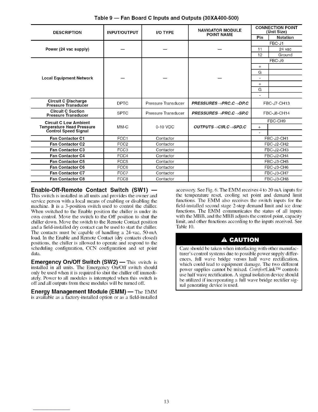
Power (24 vac supply)
Local Equipment Network
Circuit C Discharge
Pressure Transducer
Circuit C Suction
Pressure Transducer
Circuit C Low Ambient
Temperature Head Pressure
Control Speed Signal
Fan Contactor C1
Fan Contactor C2
Fan Contactor C3
Fan Contactor C4
Fan Contactor C5
Fan Contactor C6
Fan Contactor C7
Fan Contactor C8
Table 9 -- Fan Board C Inputs and Outputs (30XA400-500)
INPUWOUTPUT I/O TYPE
NAVIGATOR MODULE
POINT NAME
CONNECTION POINT
(Unit Size)
Pin I Notation
FBC-J1
11 24 vac
12 Ground
FBC-J9
+
G
DPTC Pressure Transducer PRE$SURES-_PRC.C-_DP.C FBC-J7-CH 13
SPTC Pressure Transducer PRESSURES_PRC.C_SP.C
0-10 VDC
Contactor
Contactor
Contactor
Contactor
Contactor
Contactor
Contactor
Contactor
MM-C OUTPUTS-_CIR. C--_SPD. C
FCC1
FCC2
FCC3
FCC4
FCC5
FCC6
FCC7
FCC8
FBC-J8-CH14
FBC-CH9
FBC-J2-CH1
FBC-J2-CH2
FBC-J2-CH3
FBC-J2-CH4
FBC-J3-CH5
FBC-J3-CH6
FBC-J3-CH7
FBC-J3-CH8
Enable-Off-Remote Contact Switch (SWl) --
This switch is installed in all units and provides the owner and
service person with a local means of enabling or disabling the
machine. It is a 3-position switch used to control the chillel:
When switched to tile Enable position the chiller is under its
own control. Move the switch to the Off position to shut the
chiller down. Move tile switch to tile Remote Contact position
and a field-installed dry contact can be used to start tile chiller.
The contacts must be capable of handling a 24-vac, 50-mA
load. In the Enable and Remote Contact (dry contacts closed)
positions, the chiller is allowed to operate and respond to the
scheduling configuration, CCN configuration and set point
data.
Emergency On/Off Switch (SW2) -- This switch is
installed in ;til units. The Emergency On/Off switch should
only be used when it is required to shut the chiller off immedi-
ately. Power to all modules is interrupted when this switch is
off"and all outputs from these modules will be turned off.
Energy Management Module (EMM) -- The EMM
is available as a factory-installed option or as a field-installed
accessory. See Fig. 6. The EMM receives 4 to 20 mA inputs for
the tempemtme reset, cooling set point and demand limit
functions. The EMM also receives tile switch inputs for the
field-installed second stage 2-step demand limit and ice done
functions. The EMM communicates the status of all inputs
with the MBB, and the MBB adjusts the control point, capacity
limit, and other functions according to tile inputs received. See
Table 10.
Care should be taken when interfacing with other manufac-
turer's control systems due to possible power supply differ-
ences, full wave bridge versus half wave rectification,
which could lead to equipment damage. The two diffelent
power supplies cannot be mixed. Crm_fortLink TM controls
use half wave rectification. A signal isolation device should
be utilized if incorporating a full wave bridge rectifier sig-
nal generating device is used.
13
 Loading...


