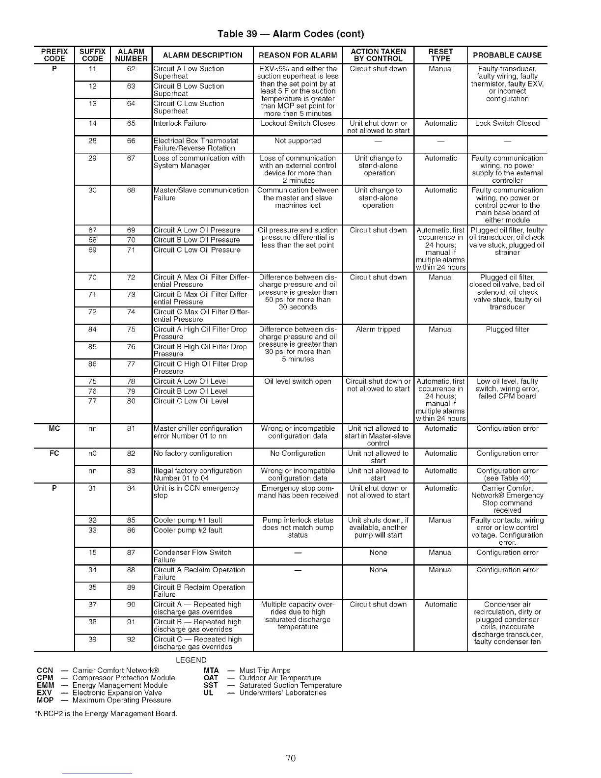
Table 39 -- Alarm Codes (cont)
PREFIX
CODE
P
SUFFIX
CODE
11
12
13
14
28
29
ALARM
NUMBER
62
63
64
65
66
67
ALARM DESCRIPTION
Circuit A Low Suction
Superheat
Circuit B Low Suction
Superheat
Circuit C Low Suction
Superheat
Interlock Failure
REASON FOR ALARM PROBABLE CAUSE
EXV<5% and either the
suction superheat is less
than the set point by at
least 5 F or the suction
temperature is greater
than MOP set point for
more than 5 minutes
Lockout Switch Closes
ACTION TAKEN
BY CONTROL
Circuit shut down
RESET
TYPE
Manual
Faulty transducer,
faulty wiring, faulty
thermistor, faulty EXV,
or incorrect
configuration
Unit shut down or Automatic Lock Switch Closed
not allowed to start
Electrical Box Thermostat Not supported -- -- --
Failure/Reverse Rotation
Loss of communication with Loss of communication Unit change to Automatic
System Manager with an external control stand-alone
device for more than operation
2 minutes
30 68 Master/Slave communication Communication between Unit change to Automatic
Failure the master and slave stand-alone
machines lost operation
Circuit shut down67
68
69
69
7O
71
Oil pressure and suction
pressure differential is
less than the set point
Difference between dis-
charge pressure and oil
pressure is greater than
50 psi for more than
30 seconds
Difference between dis-
charge pressure and oil
pressure is greater than
30 psi for more than
5 minutes
Oil level switch open
7O 72
71 73
72 74
84 75
85 76
86 77
75 78
76 79
77 80
Circuit shut down
Alarm tripped
Circuit shut down or
not allowed to start
Circuit A Low Oil Pressure
Circuit B Low Oil Pressure
Circuit C Low Oil Pressure
Automatic, first
occurrence in
24 hours;
manual if
multiple alarms
within 24 hours
Manual
Manual
Automatic, first
occurrence in
24 hours;
manual if
multiple alarms
within 24 hours
Automatic
Circuit A Max Oil Filter Differ-
ential Pressure
Circuit B Max Oil Filter Differ-
ential Pressure
Circuit C Max Oil Filter Differ-
ential Pressure
Circuit A High Oil Filter Drop
Pressure
Circuit B High Oil Filter Drop
Pressure
Circuit C High Oil Filter Drop
Pressure
Circuit A Low Oil Level
Circuit B Low Oil Level
Circuit C Low Oil Level
Faul!y communication
wiring, no power
supply to the external
controller
Faulty communication
wiring, no power or
control power to the
main base board of
either module
Plugged oil filter, faulty
oil transducer, oil check
valve stuck, plugged oil
strainer
Plugged oil filter,
closed oil valve, bad oil
solenoid, oil check
valve stuck, faulty oil
transducer
Plugged filter
Low oil level, faulty
switch, wiring error,
failed CPM board
MC nn 81 Master chiller configuration Wrong or incompatible Unit not allowed to Configuration error
error Number 01 to nn configuration data start in Master-slave
control
FC nO 82 No factory configuration No Configuration Unit not allowed to Automatic Configuration error
start
nn 83 Illegal factory configuration Wrong or incompatible Unit not allowed to Automatic
Number 01 to 04 configuration data start
P 31 84 Unit is in CCN emergency Emergency stop com- Unit shut down or Automatic
stop mand has been received not allowed to start
Manual
Pump interlock status
does not match pump
status
Unit shuts down, if
available, another
pump will start
-- None Manual
-- None Manual Configuration error
Cooler pump #1 fault
Cooler pump #2 fault
Circuit shut down
Condenser Flow Switch
Failure
Circuit A Reclaim Operation
Failure
Circuit B Reclaim Operation
Failure
Circuit A -- Repeated high
discharge gas overrides
Circuit B -- Repeated high
discharge gas overrides
Circuit C -- Repeated high
discharge gas overrides
Automatic
32 85
33 86
15 87
34 88
35 89
37 90
38 91
39 92
CON i Carrier Comfort Network®
CPM i Compressor Protection Module
EMM -- Energy Management Module
EXV -- Electronic Expansion Valve
MOP -- Maximum Operating Pressure
*NRCP2 is the Energy Management Board.
Multiple capacity over-
rides due to high
saturated discharge
temperature
LEGEND
MTA i Must Trip Amps
OAT i Outdoor Air Temperature
SST i Saturated Suction Temperature
UL i Underwriters' Laboratories
Configuration error
(see Table 40)
Carrier Comfort
Network® Emergency
Stop command
received
Faulty contacts, wiring
error or low control
voltage. Configuration
error.
Configuration error
Condenser air
recirculation, dirty or
plugged condenser
coils, inaccurate
discharge transducer,
faulty condenser fan
70
 Loading...


