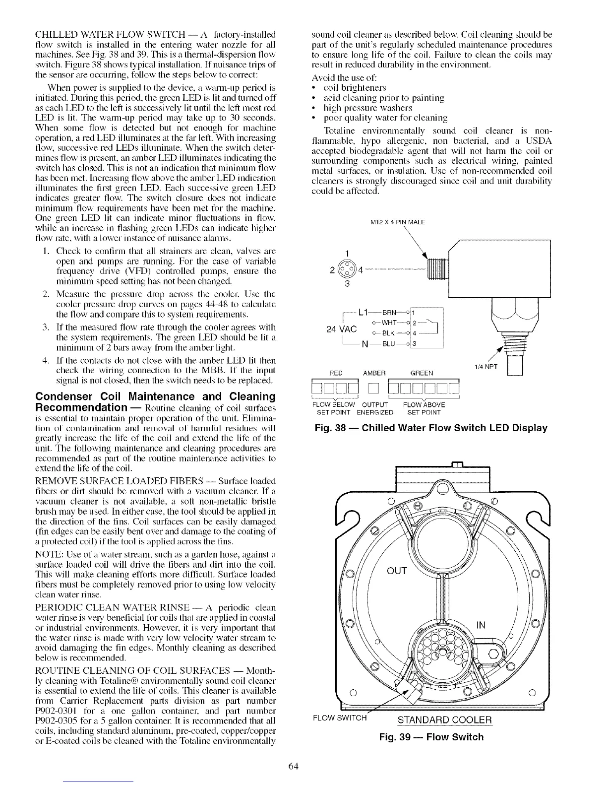
CHILLED WATER FLOW SWITCH -- A factory-installed
flow switch is installed in the entering water nozzle for all
machines. See Fig. 38 and 39. This is a thermal-dispersion flow
switch. Figure 38 shows typical installation. If nuisance trips of
the sensor me occurnng, follow the steps below to correct:
When power is supplied to the device, a warm-up period is
initiated. During this pedod, the green LED is lit trod turned off
as each LED to the left is successively lit until the left most red
LED is lit. The warm-up period may take up to 30 seconds.
When some flow is detected but not enough for machine
operation, a red LED illuminates tit the fro left. With increasing
flow, successive red LEDs illuminate. When the switch deter-
mines flow is present, an amber LED illuminates indicating the
switch has closed. This is not an indication that minimum flow
has been met. Increasing flow above the amber LED indication
illuminates the first green LED. Each successive green LED
indicates greater flow. The switch closure does not indicate
minimum flow requirements have been met for the machine.
One green LED lit can indicate minor fluctuations in flow.
while an increase in flashing green LEDs can indicate higher
flow rate, with a lower instance of nuisance alarms.
1. Check to confirm that all strainers are clean, valves me
open and pumps are running. For the case of vtuiable
frequency drive (VFD) controlled pumps, ensure the
minimum speed setting has not been changed.
2. Measure the pressure drop across the coolel: Use the
cooler pressure drop curves on pages 44-48 to ctdculate
the flow and compare this to system requirements.
3. If the measured flow rate through the cooler agrees with
the system lequirements. The green LED should be lit a
minimum of 2 bras away from the amber light.
4. If the contacts do not close with the amber LED lit then
check the wiring connection to the MBB. If the input
signal is not closed, then the switch needs to be replaced.
Condenser Coil Maintenance and Cleaning
Recommendation -- Routine cleaning of coil surfaces
is essential to maintain proper operation of the unit. Elimina-
tion of contamination and removal of harmful residues will
greatly increase the life of the coil and extend the life of the
unit. The following maintenance and cleaning procedures are
recommended as part of the routine maintenance activities to
extend the life of the coil.
REMOVE SURFACE LOADED FIBERS -- Surface loaded
fibers or dirt should be removed with a vacuum cleanel: If a
vacuum cleaner is not av_filable, a soft non-metallic bristle
brush may be used. In either case, the tool should be applied in
the direction of file fins. Coil surfaces can be easily damaged
(fin edges can be easily bent over and damage to the coating of
a protected coil) if the tool is applied across file fins.
NOTE: Use of a water stream, such as a garden hose, against a
surface loaded coil will drive the fibers and dirt into file coil.
This will make cleaning efforts more dift]cult. Surface loaded
fibers must be completely removed prior to using low velocity
clean water rinse.
PERIODIC CLEAN WATER RINSE -- A periodic clean
water rinse is very beneficial for coils that me applied in coastal
or industrial environments. Howevel, it is very important that
the water rinse is made with ve q low velocity water stream to
avoid &imaging the fin edges. Monthly cleaning as described
below is recommended.
ROUTINE CLEANING OF COIL SURFACES -- Month-
ly cleaning wifll Totaline® environmentally sound coil cleaner
is essential to extend the life of coils. This cleaner is available
from Carrier Replacement parts division as ptut number
tx)02-0301 for a one gallon container, and part number
tx)02-0305 for a 5 gallon conttfiner It is lecommended that tdl
coils, including stan&trd aluminum, pre-coated, copper/copper
or E-coated coils be cleaned with the Totaline environmentally
sound coil cleaner as described below. Coil cleaning should be
part of the unit's regularly scheduled maintenance procedures
to ensure long life of the coil. Failure to clean the coils may
result in reduced durability in the environment.
Avoid the use of:
• coil brighteners
• acid cleaning prior to painting
• high pressure washers
• poor quality water for cleaning
Tottdine environmentally sound coil cleaner is non-
flammable, hypo allergenic, non bacterial, and a USDA
accepted biodegra&tble agent that will not harm the coil or
surrounding components such as electrical wiring, painted
metal surfaces, or insulation. Use of non-recommended coil
cleaners is strongly discouraged since coil and unit durability
could be affected.
M12 X 4 PIN MALE
1
2@4
3
......................L1--BRN----o/i _............................................
I c_ WHT---o 2--
24 VAC _BLK__OI_ _
N B,u i
RED AMBER GREEN
I 1 I I
.................................v ..................................I I _ J
FLOW BELOW OUTPUT FLOW ABOVE
SET POINT ENERGIZED SET POINT
Fig. 38 -- Chilled Water Flow Switch LED Display
FLOW SWITCH STANDARD COOLER
Fig. 39 -- Flow Switch
64
 Loading...


