14
4. Clean coil using a commercial coil cleaner or dish-
washer detergent in a pressurized spray canister. Wash
both sides of coil and flush with clean water. For best
results, back --flush toward return--air section to re-
move foreign material. Flush c ondensate pan after
completion.
5. Reinstall economizer and filters.
6. Reconnect wiring.
7. Replace access panels.
THERMOSTATIC EXPANSION
VALVE (TXV)
All 50HC’s have a factory installed nonadjustable
thermostatic expansion valve (TXV). The TXV will be a
bi-flow, bleed port expansion val ve with an externa l
equalizer. TXVs are specificall y designed to operate with
PuronR or R-22 refrigera nt, use only factory authoriz ed
TXVs. Do not interchange Puron and R-22 TXVs.
TXV Operation
The TXV is a metering device that is used in air
conditioning and heat pump systems to adjust to the
changing load conditions by maintaining a preset
superheat t emperature at the outlet of the evaporator coil.
The volume of refri gerant met ered through the valve seat
is dependent upon the following:
1. Superheat temperature is sensed by cap tube sensing
bulb on suction tube at outlet of evaporator coil. This
temperature is converted into pressure by refrigera nt
in the bulb pushing downward on the diaphragm
which opens the valve using the push rods.
2. The suction pressure at the outlet of the evaporator
coil is transferred through the external equalizer tube
to the underside of the diaphragm .
3. The pin is spring loaded, which exerts pressure on the
underside of the diaphragm. Therefore, the bulb pres-
sure works against the spring pressure and evaporator
suction pressure to open the valve. If the load in-
creases, the temperature increases at the bulb, which
increases the pressure on the top side of the dia-
phragm. This opens the valve and i ncreases the flow
of refrigerant. The increased refrigerant flow c auses
the leaving evaporator temperature to decrease. This
lowers the pressure on the diaphragm and closes the
pin. The refrigerant flow is effectively stabilized to
the load demand with negligible change in superheat.
Replacing TXV
1. Recover refrigerant.
2. Remove T XV support clam p using a 5/l6-in. nut
driver.
3. Remove T XV using a wrench and an additional
wrench on connections to prevent damage to tubing.
4. Remove equalizer tube from suction line of coil. Use
file or tubing cutter to cut brazed equalizer line
approximately 2 inches above suction tube.
5. Remove bulb from vapor tube inside cabinet.
6. Install the new TXV using a wrench and an additional
wrench on connections to prevent damage to tubing
while attaching TXV to distributor.
7. Attach the equalizer tube to the suction line. If the
coil has mechanical a connection, then use a wrench
and an addit ional wrench on connections to prevent
damage. If t he coil has a brazed connection, use a file
or a tubing cutter to remove the mechanical flare nut
from the equalizer line. Then use a new coupling to
braze the equali zer line to the stub (previous equalizer
line) in suction line.
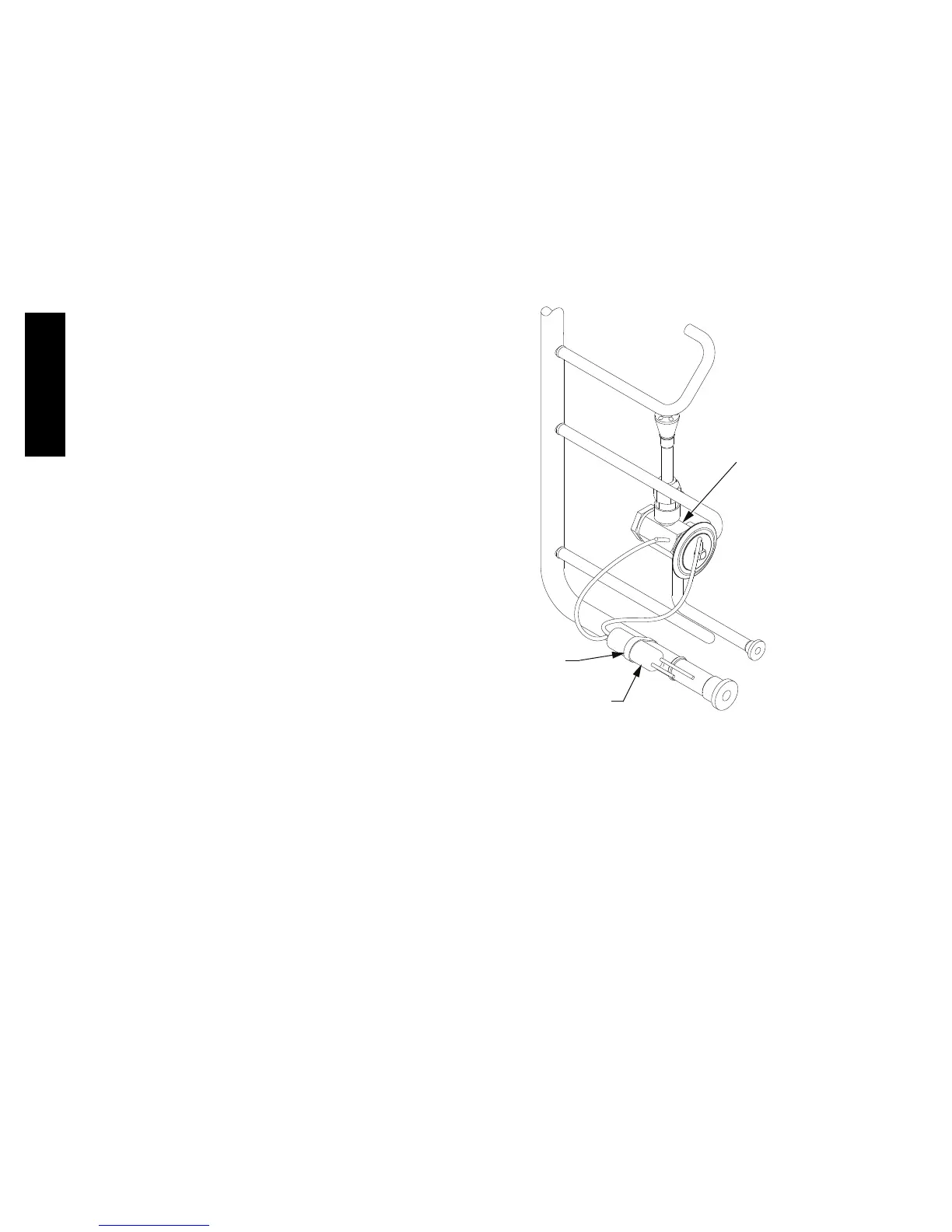
8. Attach TXV bulb in the same location where the ori-
ginal (in the sensing bulb indent) was when it was re-
moved, using the supplied bulb clamps. See Fig. 17.
TXV SENSING
BULB
CLAMP
THERMAL EXPANSION
(TXV) VALVE
SENSING BULB INSULATION REMOVED FOR CLARITY
C10372
Fig. 17 -- TXV Valve and Sensing Bulb Location
9. Route equalizer tube through suction connection
opening (large hole) in fitting panel and install fitting
panel in place.
10. Sweat the inlet of TXV marked “IN” to the liquid
line. Avoid excessive heat which could damage the
TXV valve. Use quenching cloth when applying heat
anywhere on TXV.
Refrigerant System Press ure Access Ports
There are two access ports in the system -- on the suction
tube near the compressor and on the discharge t ube near
the compressor. These are brass fittings with black plastic
caps. The hose connection fittings are standard 1/4 SAE
male flare couplings.
The brass fittings are two--piece High Flow valves, with a
receptacle base brazed to the tubing and an integral
spring--closed check valve core screwed into the base. See
Fig. 18. This check valve is permanently assembled into
this core body and cannot be serviced separately; repla ce
50HC

 Loading...
