33
Table 8 – Detector Indicators
CONTROL OR INDICATOR DESCRIPTION
Magnetic test/reset switch
Resets the sensor when it is in the alarm or trouble state. Activates or tests the sensor when it is in
the normal state.
Alarm LED Indicates the sensor is in the alarm state.
Trouble LED Indicates the sensor is in the trouble state.
Dirty LED
Indicates the amount of environmental compensation used by the sensor
(flashing continuously = 100%)
Power LED Indicates the sensor is energized.
Condenser Fan Motor Protection
The condenser fan motor is internally protected against
over--temperature.
Relief Device
A soft solder joint at the suction service access port
provides pressure relief under abnormal te mperature and
pressure conditions (i.e., fire in building). Protect this
joint during brazing operations near this joint.
Control Circuit, 24--V
The control ci rcuit is protected against overcurrent
conditions by a circ uit breaker mounted on control
transformer TRAN. Reset is manual.
C08199
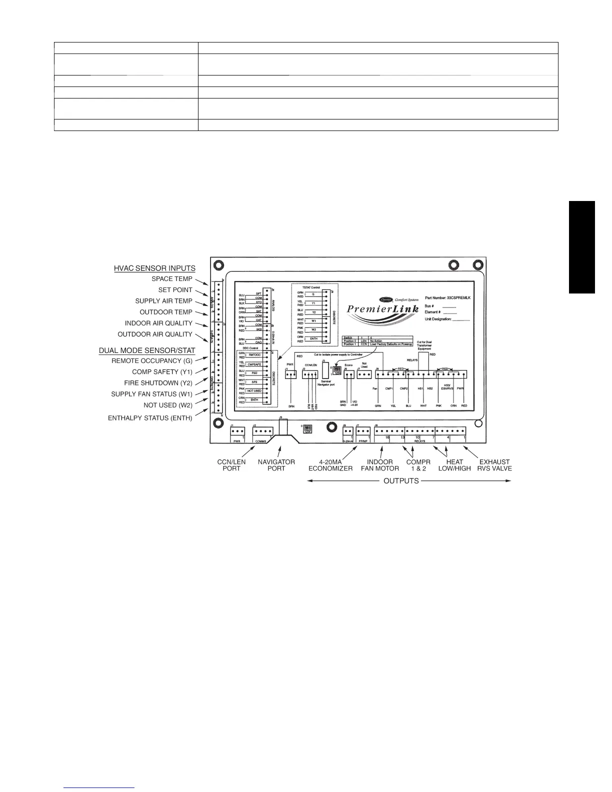
Fig. 42 -- PremierLink Controller
PREMIERLINK CONTROL
The PremierLink controller (see Fig. 42) is compatible
with Carrier Comfort Networkr (CCN) devices. This
control is designed to allow users the access and ability to
change factory--defined settings, thus expanding the
function of the standard unit control board. CCN service
access tools include System Pilott, Touch Pilott and
Service Tool. Standard tier display tools, Navigat ort and
Scrolling Marquee, are not suitable for use with the latest
PremierLink controller (Version 2.x).
The Prem ierLink control is factory--mounted in the unit’s
main control box to the left of the LCTB. Factory wiring
is compl eted through harnesses connected to the LCTB
thermostat. Field connections are made at a 16--pole
terminal block (TB1) located on the bottom shelf of the
unit control box in front of the PremierL ink controller The
factory--installe d PremierLink control includes the
supply--air tempera ture (SAT) sensor. The outdoor air
temperature (OAT) sensor is included in the
FIOP/accessory EconoMi$er 2 package.
The factory--installed PremierLink Controller includes the
supply--air tempera ture (SAT) sensor. The outdoor air
temperature (OAT) sensor is included in the
FIOP/accessory EconoMi$er 2 package.
Refer to Fig. 42 for PremierLink connection locations.
NOTE: Refer to PremierLink
t
Installation, Start--Up
and Configuration Instructions. Have a copy of this
manua l available at unit start--up.
RTU--OPEN CONTROL SYSTEM
The RTU Open controller is an integrated component of the
Carrier roofto p unit. Its internal applicatio n programming
prov id es optimum performan ce and ener gy efficien cy. RTU
Open enables the unit to run in 100% stand--alone control
mode, Carrier’s I--Vu Open network, or a Third Party
Buildin g Automatio n System (BAS ) . O n--board DIP
50HC

 Loading...
