15
the e ntire core body if necessary. Service tools are
available from RCD that allow the replacement of the
chec k valve core without having to recover the entire
system refrigerant charge. Apply compressor refrigerant
oil to the check valve c ore’s bottom o--ring. Instal l the
fitting body with 96 10 in--lbs (10.85 1.1 Nm) of
torque; do not overtighte n.
PURONR (R--410A) REFRIGERANT
This unit is designed for use with Puron (R--410A)
refrigerant. Do not use any other re frigerant in this
system. Puron (R--410A) refrigerant is provided in pink
(rose) colored cyl inders.
Puron (R--410A) re frigerant is provided in pi nk (rose)
colored cylinders. These cylinders are available with and
without dip tubes; c ylinders with dip tubes will have a
labe l indi cating this feature. For a cylinder with a dip
tube, place the cylinder in the upright position (access
valve at the top) when removing liquid refrigerant for
charging. For a cylinder without a dip tube, invert the
cylinder (access valve on the bottom) when removing
liquid refrigerant.
Because Puron (R--410A) refrigerant is a blend, it is
strongly recommended that refrigerant always be removed
from the cyl inder as a liquid. Admit li quid refrigerant into
the system in the discharge line. If adding refrigerant into
the suction line, use a commercial metering/expansion
devic e at the gauge manifold; remove liquid from the
cylinder, pass it through the metering device at the gauge
set and then pass it into the suction line as a vapor. Do not
remove Puron (R--410A) refrigerant from the cylinder as a
vapor.
Refrigerant Charge
Amount of refrigerant charge is listed on the unit’s
nameplate. Refer to Carrier GTAC2--5 Charging,
Recovery, Recycling and Reclamation training manual
and the foll owing procedures.
Unit panel s must be in place when unit is operating during
the cha rging procedure .
No Charge
Use standard evacuating techniques. After evacuating
system, weigh in the specified amount of refrigerant.
Low-- Charge Cooling
Using Cooling Charging Charts, Fig. 19 through Fig. 26,
vary refrigerant until the conditions of the appropriate
chart are met. Note the charging charts are different from
type normally used. Charts are based on charging the units
to the correct sub--c ooling for the various operating
conditions. Accurate pressure ga uge and temperat ure
sensing device are required. Connect the pressure gauge to
the service port on the liquid line . Mount the te mperature
sensing device on the liquid line and insulate it so that
outdoor ambient temperature does not affect the reading.
Indoor--air cfm must be within the normal operating range
of the unit.
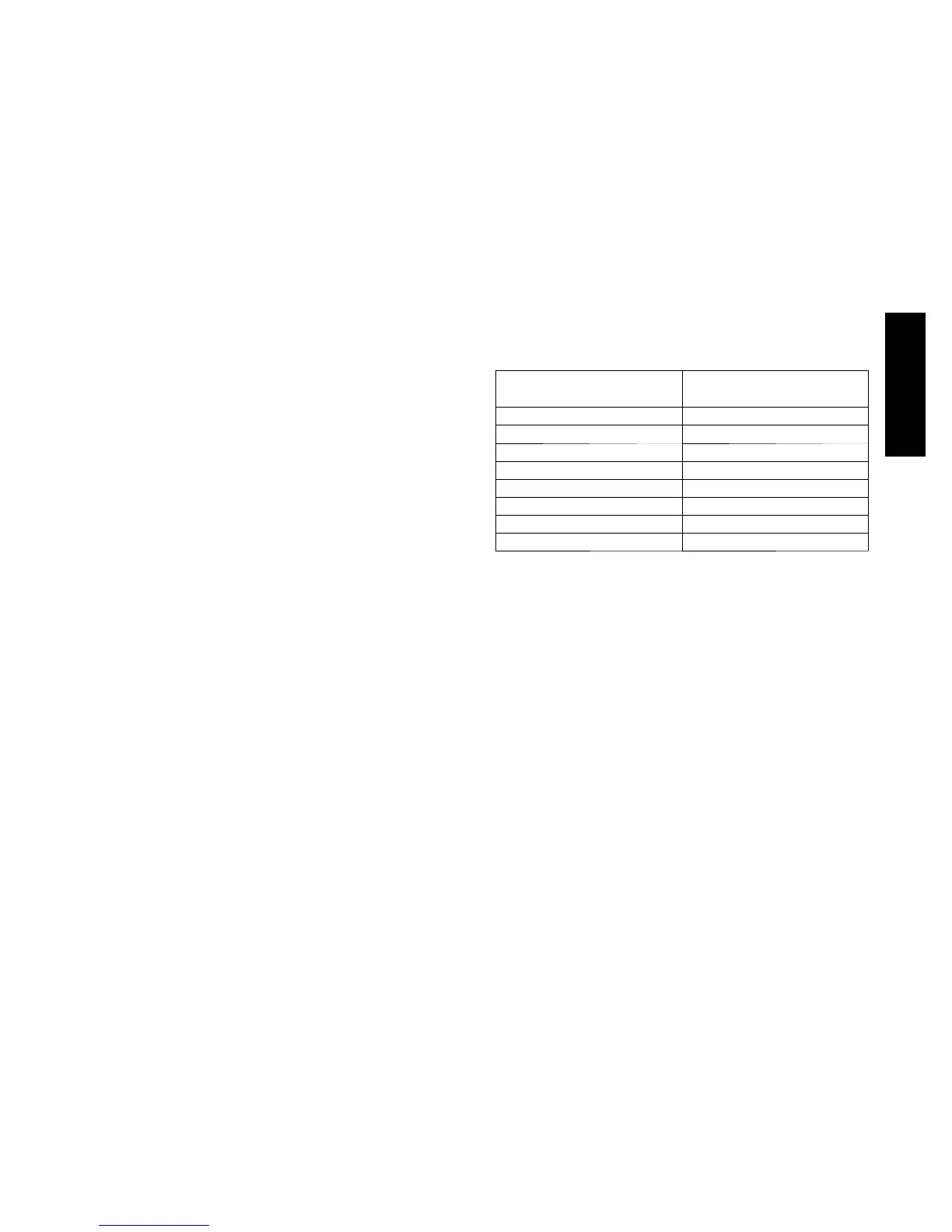
SIZE DESIGNATION NOMINAL TONS
REFERENCE
04 3
05 4
06 5
07 6
08 7.5
09 8.5
12 10
14 12.5
EXAMPLE:
Model 50HC*A04
Outdoor Temperature 85_F(29_C)..................
Suction Pressure 140 psig (965 kPa).................
Suction Temperature should be 60_F(16_C)..........
Using Cooling Charging Charts
Take the outdoor ambient temperat ure and rea d the liquid
pressure gauge. Refer to chart to determine what liquid
temperature should be. If liquid temperature is low, add
refrigerant. If liquid temperature is high, carefully rec over
some of the charge. Recheck the liquid pressure as charge
is adjusted.
50HC

 Loading...
