41
Indoor Air Quality (IAQ) Sensor Input
The IAQ input can be used for demand control ventilation
control based on the level of CO
2
measured in the space
or return air duct.
Mount the accessory IAQ sensor according to
manufacturer specifications. The IAQ sensor should be
wired to the AQ and AQ1 terminals of the controller.
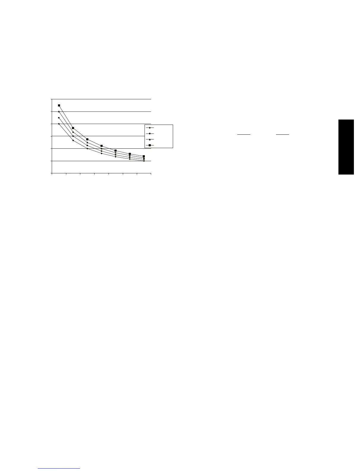
Adjust the DCV potentiometers to correspond to the DCV
voltage output of the indoor air quality sensor at the
user-determined setpoint. See Fig. 56.
0
1000
2000
3000
4000
5000
6000
2345678
800 ppm
900 ppm
1000 ppm
1100 ppm
RANGE CONFIGURATION (ppm)
DAMPER VOLTAGE FOR MAX VENTILATION RATE
CO SENSOR MAX RANGE SETTING
2
C06039
Fig. 56 -- CO
2
Sensor Maximum Range Settings
If a separate field-supplied transformer is used to power
the IAQ sensor, the sensor must not be grounded or the
EconoMi$er IV control board will be damaged.
When using demand ventilation, the minimum damper
position represents the minimum ventilation position for
VOC (volatile organic compounds) ventilation
requirements. The maximum demand ventilation position
is used for fully occupied ventilation.
When demand ventilation control is not being used, the
minimum position potentiometer should be used to set the
occupied ventilation position. The maximum demand
ventilation position should be turned fully clockwise.
Exhaust Setpoint Adjustment
The exhaust setpoint will determine when the exha ust fan
runs based on damper position (if accessory power
exhaust is install ed). The setpoint is modified with the
Exhaust Fan Setpoint (EXH SET) potentiometer. See Fig.
50. The setpoint represents the damper position above
which the exhaust fans will be turned on. When there is a
call for exhaust, the EconoMi$er IV controller provides a
45
15 second delay before exhaust fan activation to
allow the dampers to open. This delay allows the damper
to reach the appropriate position to avoid unnecessary fan
overload.
Minimum Position Control
There is a minimum damper position potentiometer on the
EconoMi$er IV controlle r. See Fig. 50. The minimum
damper position maintains the minimum airflow into the
building during the occupied period.
When using demand ventilation, the minimum damper
position represents the minimum ventilation position for
Volatile Organic Compound (VOC) ventilation
requirements. The maximum demand ventilation position
is used for fully occupied ventilation.
When demand ventilation control is not being used, the
minimum position potentiometer should be used to set the
occupied ventilation position. The maximum demand
ventilation position should be turned fully clockwise.
Adjust the minimum position potentiometer to allow the
minimum amount of outdoor air, as required by local
codes, to enter the building. Make minimum position
adjustments with at least 10_F temperature difference
betwee n the outdoor and return-air temperatures.
To determine the minimum position setting, perform the
following procedure:
1. Calculate the appropriat e mixed air temperature
using the following formula:
(T
Ox
OA
)
+(TR
x
RA
)=T
M
100 100
T
O
= Outdoor-Air Temperature
OA = Perc ent of Outdoor Air
T
R
= Return-Air Temperature
RA = Percent of Return Air
T
M
= Mixed-Air Temperature
As an example, if local codes require 10% outdoor
air during occupied conditions, outdoor-air
temperature is 60_F, and return-air temperature is
75_F.
(60 x .10) + (75 x .90) = 73.5_F
2. Disconnect the supply air sensor from terminals T
and T1.
3. Ensure that the factory-installed jumper is in place
across terminals P and P1. If remote damper
positioning is being used, make sure that the
terminals are wired according to Fig. 52 and that the
minimum position potentiometer is turned fully
cloc kwise.
4. Connect 24 vac across term inals TR and TR1.
5. Carefully adjust the minimum position
potentiometer until the measured mixed air
temperature matches the calculated value.
6. Reconnect the supply air sensor to terminals T and
T1.
Remote control of the E conoMi$er IV damper is desirable
when requiring additional temporary ventilation. If a
field-supplied remote potentiometer (Honeywell p/n:
S963B1128) is wired to the EconoMi$er IV controller, the
minimum position of the damper can be controlled from a
remote location.
To control the minimum damper position remotely,
remove the factory-installed jumper on the P and P1
terminals on the EconoMi$er IV controller. Wire the
field-supplied potentiometer to the P and P1 terminals on
the Ec onoMi$er IV controller. (See Fig. 55.)
Damper Movement
Damper movement from full ope n to full closed (or vi ce
versa) take s 2
1
/
2
minutes.
50HC

 Loading...
