5
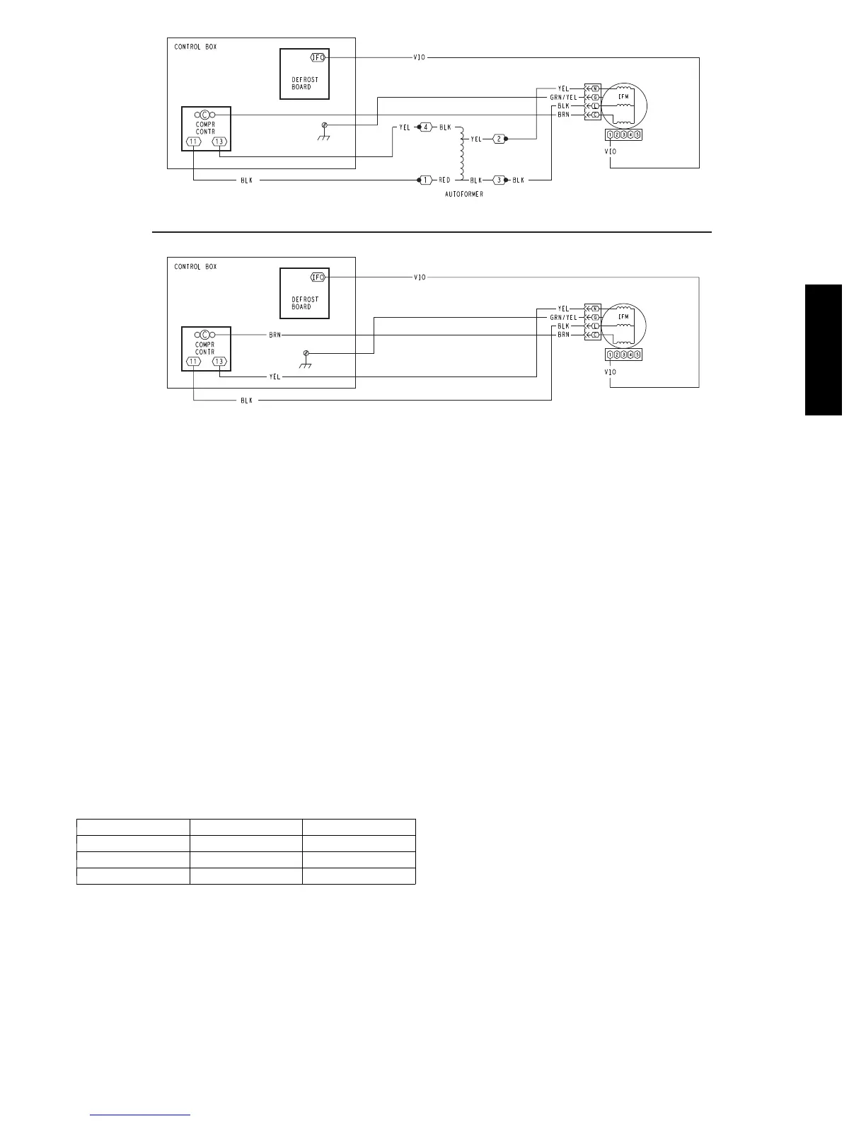
460, 575-v Units
208/230-v Units
C09260
Fig. 5 -- Direct--Drive Supply Fan Assembly
Motor “rocking” on star t--up — When the motor first
starts, the rotor (and attached wheel) will “rock” back and
forth as the motor tests for rotational direction. Once the
correct rotational direction is determined by the motor
circuitry, the motor will ramp up to the specified speed.
The “rocking” is a normal operating characteristic of
ECM motors.
Troubleshooting the ECM motor — Troubleshooti ng the
X13 ECM requires a voltmeter.
1. Disconnect main power to the unit.
2. Remove the motor power plug (including the control
BRN l ead) and VIO control signal lead at the motor
terminals.
3. Restore main unit power.
4. Check for proper line voltage at motor power leads
BLK (at L terminal) and YEL (at N terminal). See
Table 2.
Table 2 – Motor Test Volts
Unit Voltage Motor Voltage Min---Max Volts
208/230 230 190--- 250
460 230 210--- 250
575 460 420--- 500
5. Using a jumper wire from unit control terminals R to
G, engage motor operation. Check for 24v output at
the defrost board terminal IFO.
6. Check for proper c ontrol signal voltages of 22V to
28V at motor signal leads VIO and BRN.
7. Disconnect unit main power. Apply lockout/tagout
procedure s.
8. Reconnect m otor power and control signal leads at
the motor terminals.
9. Restore unit main power.
10. The motor should start and run. If the motor does not
start, remove the motor assembly. Replace the motor
with one having t he same part number. Do not
substitute with an alternate design motor as the
torque/ speed programming will not be the same as
that on an origi nal factory motor.
Replacing the X--13 ECM Motor — Before removing
the ECM belly --band mounting ring from old motor:
1. Measure the distance from base of the motor shaft to
the edge of the mounting ring.
2. Remove the motor mounting band and transfer it to
the replacement motor.
3. Position the mounting band at the same distance that
was measured in Step 1.
4. Hand--tighten mounting bolt onl y. Do not tighte n
securely at this time.
5. Insert the motor shaft into the fan wheel hub.
6. Securely tighten the three motor mount arms to the
support cushions and torque the arm mounting screws
to 60 in--lbs (6.8 Nm).
7. Center the fan wheel in the fan housing. Tighten the
fan wheel hub setscrew and torque to 120 in--lbs (13.6
Nm).
8. Ensure the motor terminals are located at a position
below the 3 o’clock position (see Fig. 3). Tighten the
motor be lly--band bolt and torque to 80 in--lbs (9.0
Nm).
Supply Fan (Belt--Drive)
The belt--drive supply fan system consists of a
forward--curved centrifugal blower wheel on a solid shaft
with two concentric type bearings, one on each side of the
50HC

 Loading...
