30
Dirty Sensor Test Procedure
1. Hold the test magnet where indicated on the side of
the sensor housing for two seconds.
2. Verify that the sensor’s Dirty LED flashes.
OPERATIONAL TEST ALERT
Failure to follow this ALERT can result in an
unnecessary evacuation of the facility.
Changing the dirty sensor test operation will put the
detector into the alarm state and activate all automatic
alarm responses. Before changing dirty sensor test
operation, disconnect all auxiliary equipment from the
controller and notify the proper authorities if
connected to a fire alarm system.
NOTICE
Changing the Dirt Sensor Test
By default , sensor dirty test results are indicated by:
S The sensor ’s Dirty LED flashing.
S The controller’s Trouble LED flashing.
S The controller’s supervision rel ay contacts toggle.
The operat ion of a sensor’s dirty test can be changed so
that the controller ’s supervision relay is not used to
indicate test results. When two detectors are connected to
a controller, sensor dirty test operation on both sensors
must be configure d to ope rate in the same manner.
To Configure the Dirty Sensor Test Operation
1. Hold the test magnet where indicated on the side of
the sensor housing until the sensor’s Alarm LED turns
on and its Dirty LED flashes twice (approximately 60
seconds).
2. Reset the sensor by removing the test magnet then
holding it against the sensor housing aga in until the
sensor’s Alarm LED turns off (approximately 2
seconds).
Remote Station Test
The remote station alarm test checks a test/reset station’s
ability to initiate and indicate an alarm state.
OPERATIONAL TEST ALERT
Failure to follow this ALERT can result in an
unnecessary evacuation of the facility.
This test places the duct detector into the alarm state.
Unless part of the test, disconnect all auxiliary
equipment from the controller before performing the
test. If the duct detector is connected to a fire alarm
system, notify the proper authorities before
performing the test.
NOTICE
SD--TRK4 Remote Alarm Test Procedure
1. Turn the key switch to the RESET/TEST position for
seven seconds.
2. Verify that the test/reset station’s Alarm LED turns
on.
3. Reset the sensor by turning the key switch t o the
RESET/TEST position for two seconds.
4. Verify that the test/reset station’s Alarm LED turns
off.
Remote Test/Reset Station Dirty Sensor Test
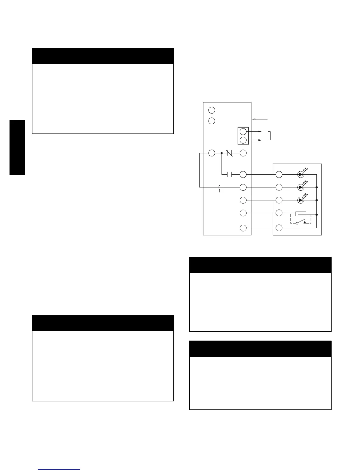
The test/reset station dirty sensor test checks the test/reset
station’s ability to initiate a sensor dirty test and indicate
the results. It must be wired to the controller as shown in
Fig. 39 and configured to operate the controll er’s
supervision relay. For more information, see “Changing
sensor dirty test operation.”
1
12
14
1
3
19
15
2
20
3
Reset/Test
Trouble
P
ower
Alarm
S
upe
rv
ision relay
contacts [3]
5
4
1
3
2
SD-TRK4
2
1
TB3
18 Vdc ( )
+
18 Vdc ( )
−
Auxiliary
equipment
+
−
W
ire must be
added by installer
Smoke Detector Controller
C08247
Fig. 39 -- Remote Test/Reset Station Connections
OPERATIONAL TEST ALERT
Failure to follow this ALERT can result in an
unnecessary evacuation of the facility.
If the test/reset station’s key switch is left in the
RESET/TEST position for longer than seven seconds,
the detector will automatically go into the alarm state
and activat e all automatic alarm responses.
NOTICE
OPERATIONAL TEST ALERT
Failure to follow this ALERT can result in an
unnecessary evacuation of the facility.
Holding the test magnet to the target area for longer
than se ven seconds will put the detector into the alarm
state a nd a ctivate all automatic alarm responses.
NOTICE
Dirty Sensor Test Using an SD--TRK4
1. Turn the key switch to the RESET/TEST position for
two seconds.
50HC

 Loading...
