31
2. Verify that the test/reset station’s Trouble LED
flashes.
Detector Cleaning
Cleaning the Smoke Detector
Clean the duct smoke sensor when the Dirty LED is
flashing continuously or sooner if conditions warrant.
OPERATIONAL TEST ALERT
Failure to follow this ALERT can result in an
unnecessary evacuation of the facility.
If the smoke detector is connected to a fire alarm
system, first notify the proper authorities that the
dete ctor is unde rgoing mainte nance then disable the
relevant circuit to avoid generating a false alarm.
NOTICE
1. Disconnect power from the duct detector then remove
the sensor’s cover. See Fig. 40.
Airow
HVAC duct
Sampling
tube
Retainer
clip
Optic
plate
Optic
housing
Sensor
housing
C07305
Fig. 40 -- Sensor Cleaning Diagram
2. Using a vacuum cleaner, clean compressed air, or a
soft bristle brush, remove loose di rt and debris from
inside the sensor housing and cover.
Use isopropyl alcohol and a lint--free cloth to remove
dirt a nd other c ontaminants from the gasket on the
sensor’s cover.
3. Squeeze the retainer clips on both sides of the optic
housing.
4. Lift the housing away from the printed circuit board.
5. Gently remove dirt and debris from around the optic
plate and inside the opt ic housing.
6. Replace the optic housing and sensor cover.
7. Connect power to the duc t detector then perform a
sensor alarm test.
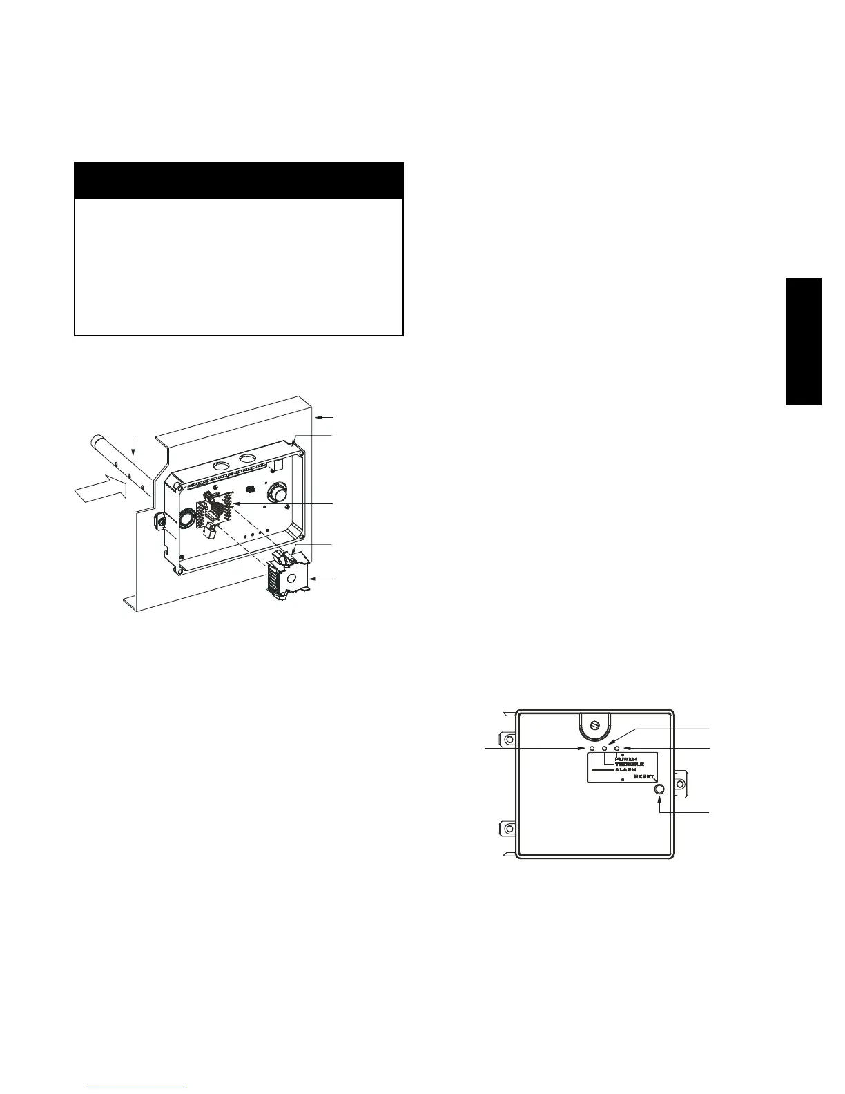
Indicators
Normal State
The smoke dete ctor operates in the normal state in the
absence of any trouble conditions and when its sensing
chamber is free of smoke. In the normal state, the Power
LED on both the sensor and t he controller are on and all
other LE Ds are off.
Alarm State
The smoke detector enters the ala rm state when the
amount of smoke pa rticulate in the sensor’s sensing
chamber exceeds the alarm threshold value. (See Table 8.)
Upon entering the alarm state:
S The sensor ’s Alarm LED and the controller’s Alarm
LED turn on.
S The contacts on the controller’s two auxiliary relays
switch positions.
S The contacts on the controller’s alarm initiation relay
close.
S The controller’s re mote alarm LED output is activated
(turned on).
S The controller’s high impedance multiple fan shutdown
control line is pulled to ground Trouble state.
The SuperDuct duct smoke detector enters the trouble
state under the following conditions:
S A sensor’s cover is removed and 20 minutes pass before
it is properly secured.
S A sensor’s environmental compensation limit is reached
(100% dirty).
S A wiring fault between a sensor and the controller is
detected.
An i nternal sensor fault is detected upon entering the
trouble sta te:
S The contac ts on the controller’s supervisory relay
switch positions. (See Fig. 41.)
S If a sensor trouble, the sensor’s Trouble LED the
controller’s Trouble LED turn on.
S If 100% dirty, the sensor’s Dirty LED turns on and the
controller’s Trouble LED flashes conti nuously.
S If a wiring fault between a sensor and the controller, the
controller’s Trouble LED turns on but not the sensor’s.
Alarm
Power
Test/reset
switch
Trouble
C07298
Fig. 41 -- Controller Assembly
NOTE: All troubles are latche d by the duct smoke
detector. The trouble condition must be cleared and then
the duct smoke detec tor must be reset in order to restore it
to the normal state.
Resetting Alarm and Trouble Condition Trips:
Manual reset is required to restore smoke detector systems
to Normal operation. For installations using two sensors,
50HC

 Loading...
