8 Chromalox 2104 Technical Manual
Thermocouple Inputs
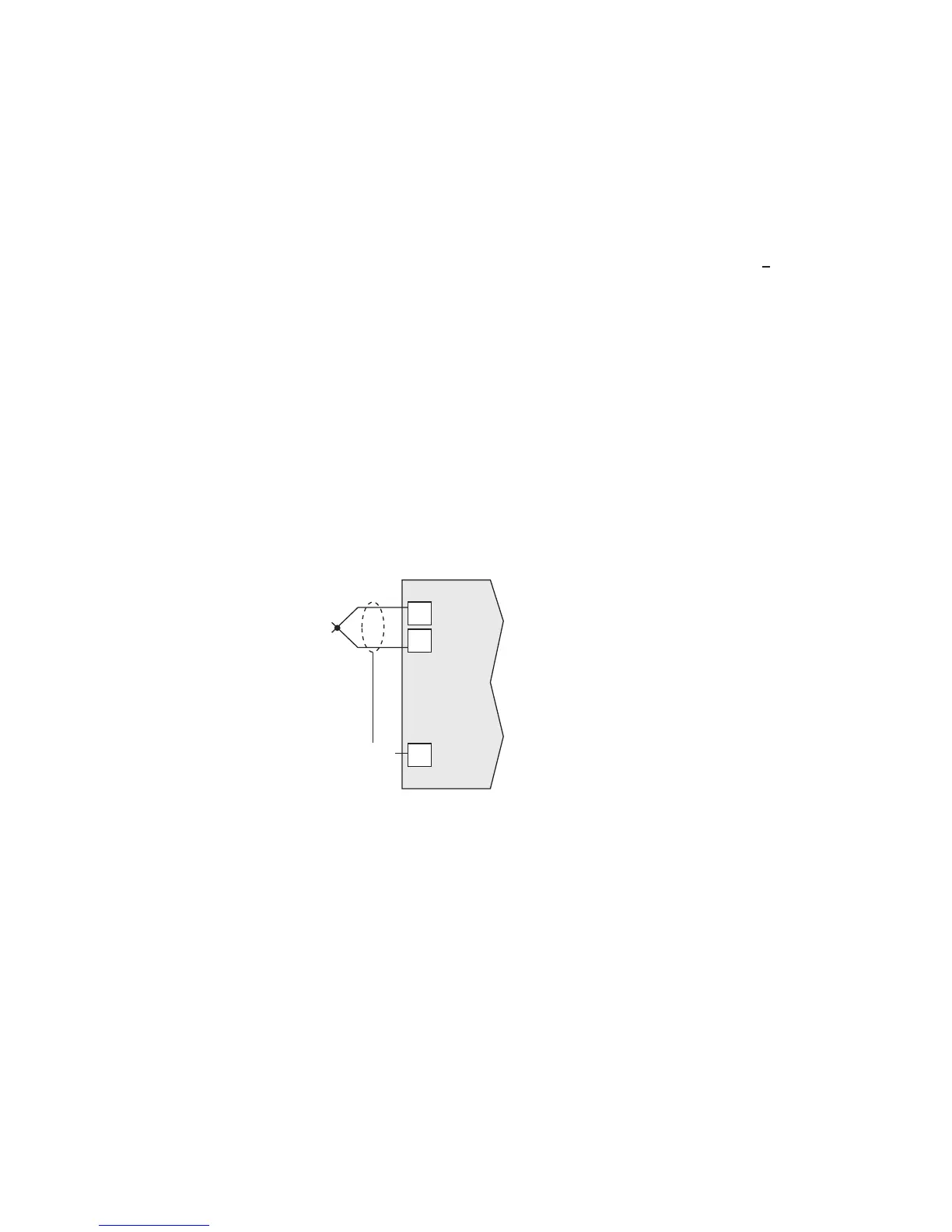
It is important to observe polarity (+, -) when
connecting thermocouple leadwires. The table
below shows ANSI color coding for the
thermocouples used with this instrument.
Make the thermocouple wiring connections to
terminals as shown in Figure 2.5.
T/C Type Material Polarity (+) Polarity (-)
B Plat, 30% Rhodium/ Gray Red
Plat, 6% Rhodium
J Iron/Constantan White Red
K Chromel/Alumel Yellow Red
E Chromel/Constantan Purple Red
T Copper/Constantan Blue Red
R Plat, 13% Rhodium/Plat Black Red
S Plat, 10% Rhodium/Plat Black Red
Figure 2.5
Thermocouple
Connections
3-Wire RTD Inputs
When making the 3-wire RTD input connection, it is
important to make the resistance of all three extension
leadwires equal by using the same gauge and same
length of wire for optimum leadwire compensation.
Chromalox recommends 3-wire RTDs for greatest
accuracy, and standard shielded copper wire for RTD
extensions. Make 3-wire RTD connections to
terminals 7, 8 and 9 as shown in Figure 2.6 on the
following page.
8
9
+
-
Shield Gnd
18
2104

 Loading...
