Chromalox 2104 Technical Manual 11
The 2104 is supplied with either:
•1 Control Output for Single Output
Control (#1)
•2 Control Outputs for Heat/Cool Control
(#1 and #2)
The output wiring varies depending on the control
type and applications. The wiring instructions are
presented separately for each of these two controller
types/applications.
Output
Wiring
Warning
Incorrect output wiring may cause system/process
damage.
☛
Single Output Control Wiring
Relay Output
Output Code “RO” on the 2104 (2104 - RO***)
gives you the option of SSR Drive or Relay control
for output #1. When shipped from the factory, the
relay output is active.
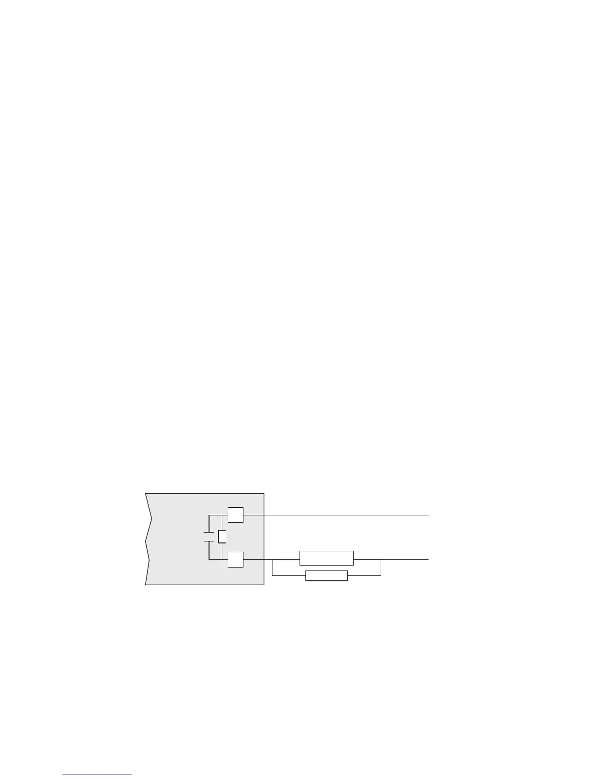
Figure 2.13
Relay Output Connections
SSR Drive Output
For SSR drive output applications, you must move
an internal jumper on the Output #1 module to
select SSR drive output. Remove the controller from
its housing, and locate the output module as shown
in Figure 2.14 on the following page. Reposition the
jumper to select SSR Drive output.
120 or 230 Vac
AC Neutral
10
11
{
Relay
Contacts
Load
Snubber
Internal
MOV

 Loading...
