22 Chromalox 2104 Technical Manual
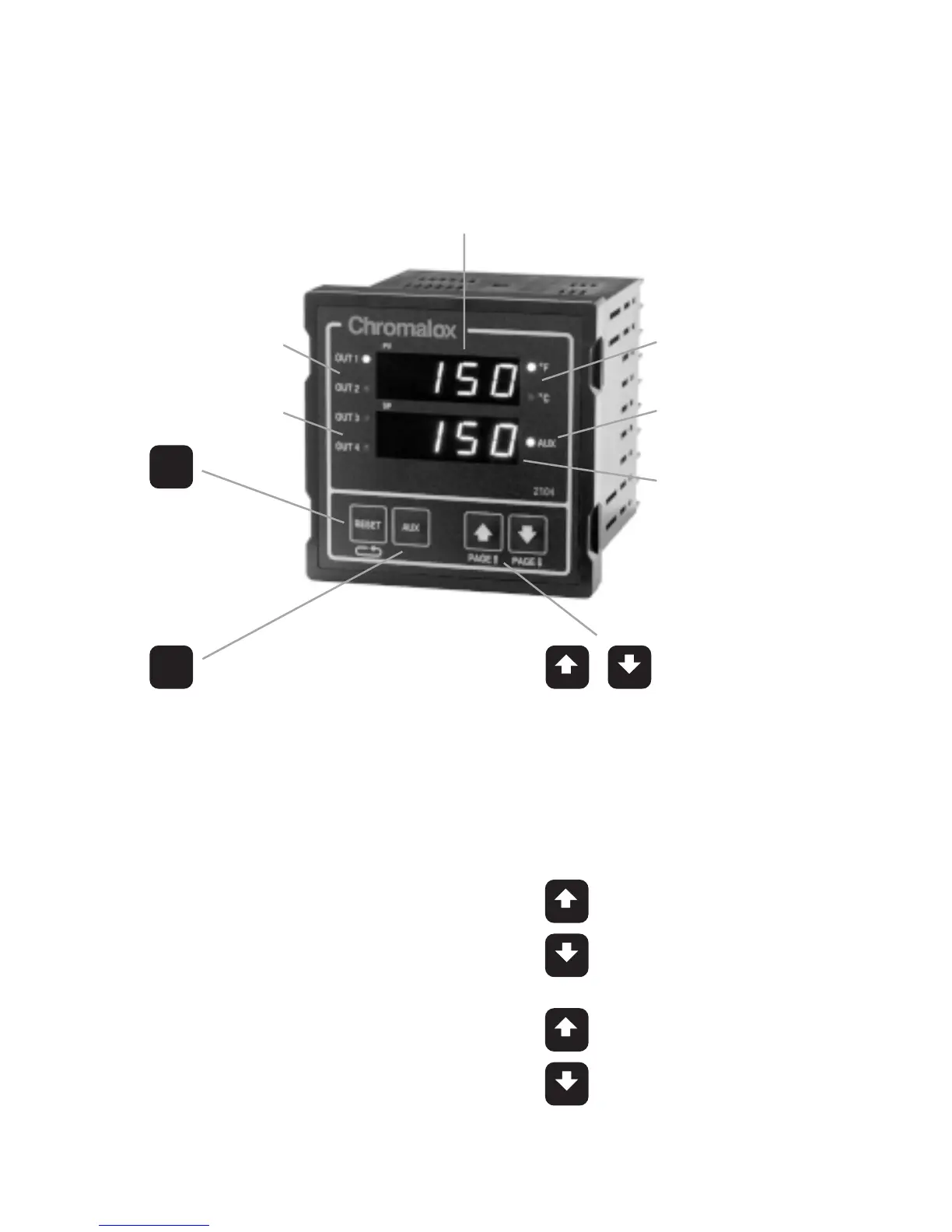
Figure 3.1
Front Panel
Identification
LEDs indicate Control
Output #1 or #2 ON
LEDs indicate Alarm
or Event Output ON
LEDs indicate °F
or °C selected for
Process Variable
LED indicates an
Auxiliary function
is active
Active Setpoint
Display
RESET
Pushbutton
•Reset Latching Alarm
•Hold for more than
3 seconds to enter or
exit Setup Mode
•Scrolls through
MENUs in
Setup Mode
AUX
Programmable Pushbutton
•PID1/PID2 Toggle Switch
•Auxiliary Setpoint Enable
•Remote Setpoint Enable
•Output Disable
•Ramp/Soak Operations
•Auto/Manual Selector
•Process Variable Display in
Normal Display Mode
•Alphanumeric Menu display
in Setup Mode
•In Normal Display Mode,
pushbuttons adjust Setpoint.
•In Setup Mode, pushbuttons
increase/decrease MENU
values.
•Ramp to Setpoint, press once to
determine target setpoint.
•For Ramp/Soak Operation:
Start
Hold
}
Press together
to Stop

 Loading...
