Procedure
Step 1
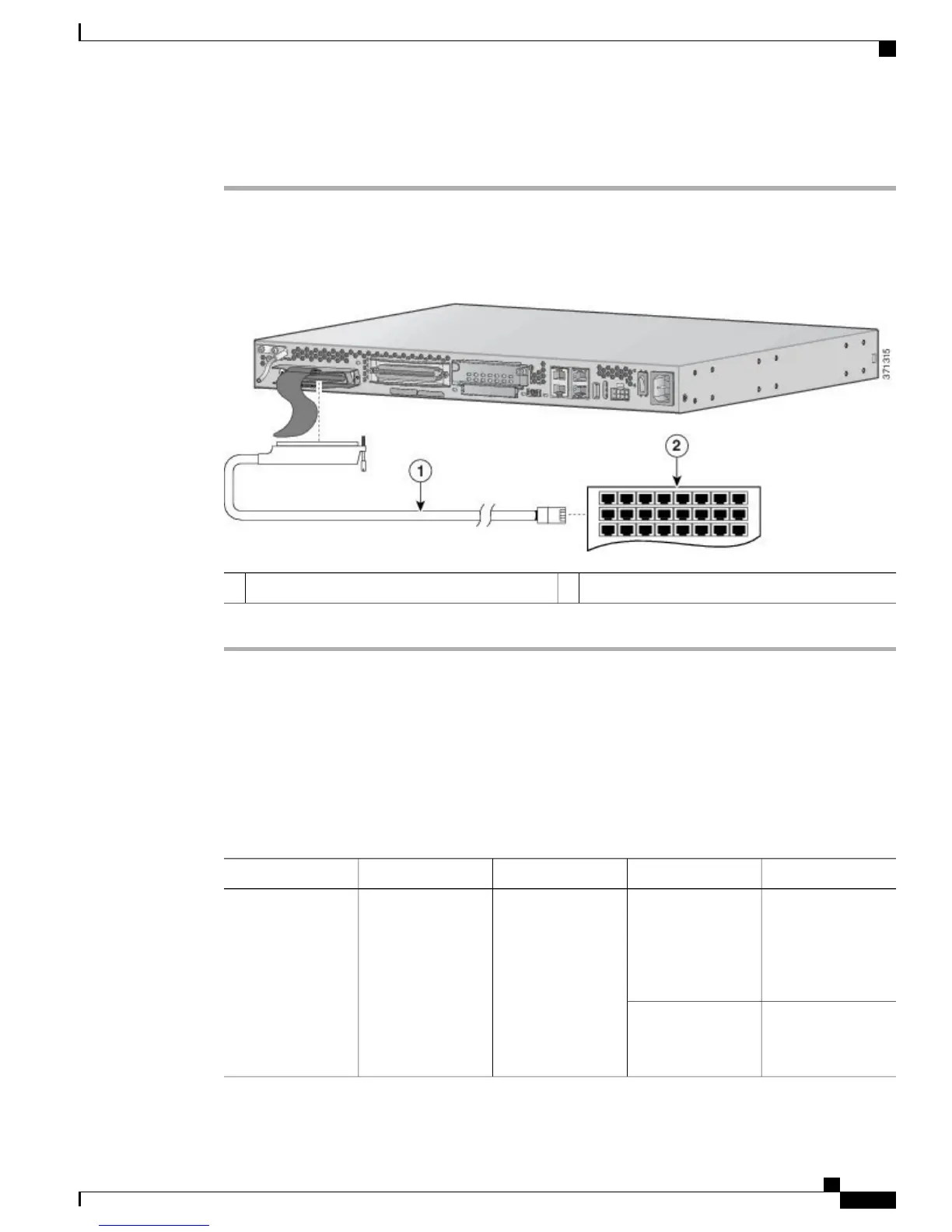
Connect the RJ-21 cable from the analog voice multiport to the distribution panel.
Step 2
Secure the cable in place using the strap.
Figure 18: Analog Voice Connection
Distribution panel2RJ-21 cable1
Ports, Connectors, and Pinouts
The following table summarizes the cable connections between the voice gateway and the network and user
interfaces. Find the port and the equipment or network type in the table and then look at the applicable pinout
table in Cable Specifications and Information, on page 69.
Table 12: Reference Guidelines for Cable Usage
Pinout InformationInterface ToConnector/CablePort ColorVoice Gateway Port
Console and
Auxiliary Port
Signals and
Pinouts, on page
69
PCRJ-45/RolloverLight blueConsole
Console Port to
ASCII Terminal, on
page 72
ASCII terminal
Cisco VG310 and Cisco VG320 Voice Gateways Hardware Installation Guide
OL-31292-01 47
Installing the Cisco VG310 and Cisco VG320 Voice Gateways
Ports, Connectors, and Pinouts
 Loading...