Page 45
SYSTEM COMPONENT CONFIGURATION
The radiant zone module must be configured via thermostat depending
on the components connected to the outputs.
RADIANT ZONE MODULE - CONFIGURATION
Parameters to be modified
Channel Parameter Value
1 P02
2 P03
......... .....
6 P07
0 = Disabled
1 = Thermoregulation 1G
2 = Thermoregulation 2 G
3 = I/O
4 = Relay control ID
5 = Thermostat Module
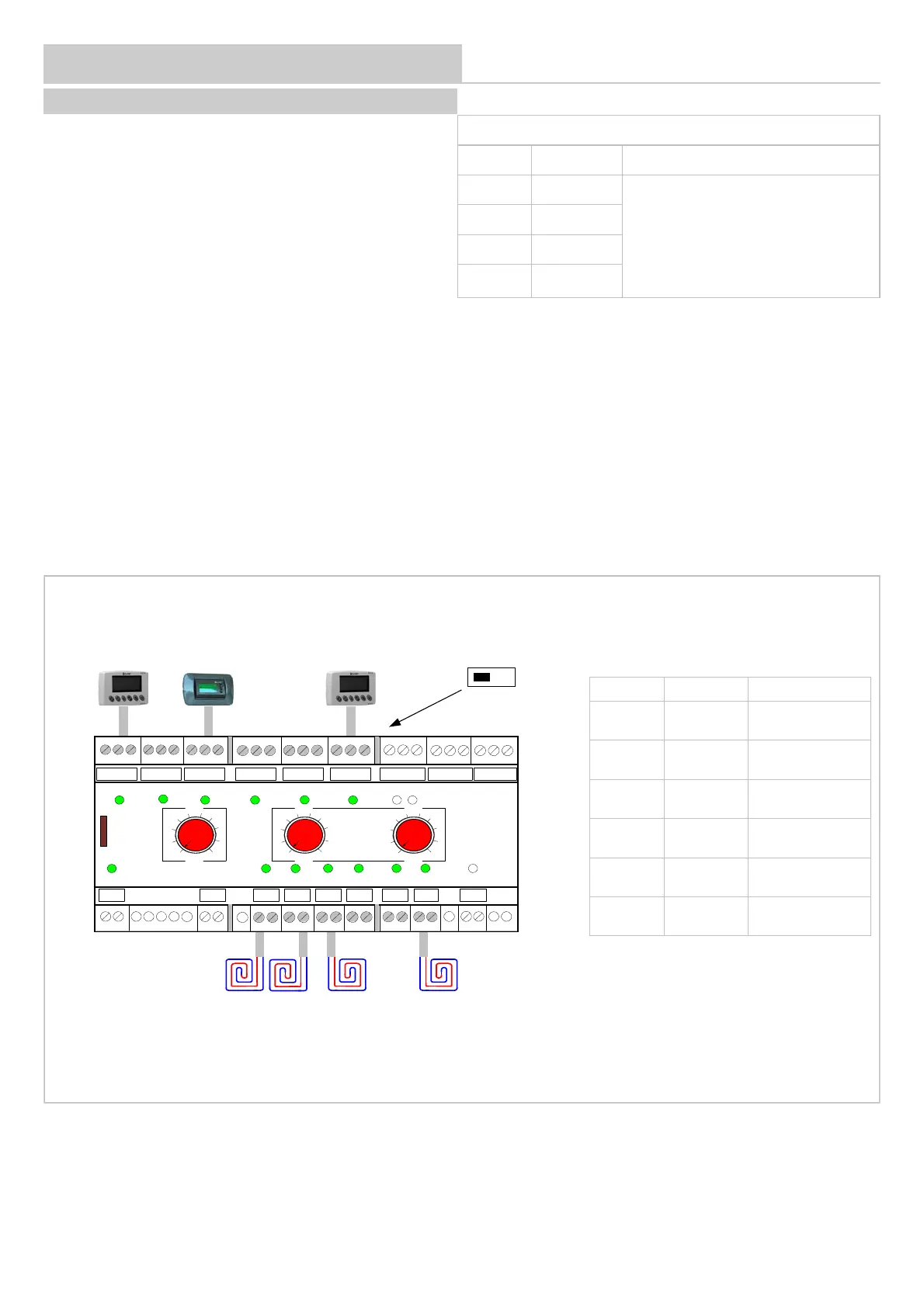
Configuration via thermostat:
Verify that the front selector switch of the ADDRESSES are set in position zero, otherwise addresses cannot be entered using the thermostats.
1 - switch off the module
2 - connect a HID-T2, HID-T3 or HID-TI2 thermostat to channel 6
3 - move the dip-switch placed under channel 6 connectors in position ON
4 - switch on the module, the word OFF is displayed on the thermostat
5- configure the parameters corresponding to the used channels
6 - follow the instruction at page 51 or 52
7 - once the addressing is complete, move the dip-switch placed under channel 6 connectors in position OFF
Channel Parameters Description
1 P02 = 2
Thermoregulation 2
Steps
2 P03 = 0 Disabled
3 P04 = 1
Thermoregulation 1
Step
4 P05 = 0 Disabled
5 P06 = 0 Disabled
6 P07 = 1
Thermoregulation 1
Step
12
3
6
HID-T3 HID-TI2
54
HID-T2
12
354
6
230V
LN
BT1 BT2
RS 485CH 1 CH 2 CH 3 CH 4 CH 5
CH 6
COMID1 ID2 COM
GND
+-
GND
+-
GND
+-
GND
+-
GND
+-
GND
+-
GND
+-
G G0 G1G0 G2 G0 G3G0 G4G0 G5 G0 G6G0 C1NO1
G1 G2
G3 G4
G5
G6
AUX
ID1 ID2CH5 CH6CH4CH3CH2CH1
PWR
ZONE X 10 X 1
1
0
2
3
4
5
6
7
8
9
1
0
2
3
4
5
6
7
8
9
1
0
2
3
4
5
6
7
8
9
ADDRESS
ON OFF
Example:
 Loading...