Page 54
SYSTEM COMPONENT ADDRESSING
RADIANT ZONE MODULE
The addressing can occur:
• Via selector switches
• Via thermostats
Addressing with selector switches
Example to assign address 12:
Selector switch A = 1, selector switch B = 2
HID-T2 Temperature
HID-T3 Temp. + humidity
HID-TI2 Temperature
uncased
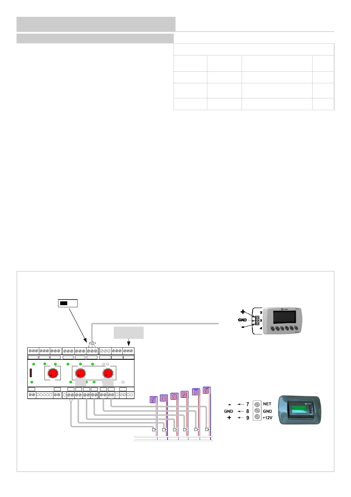
Addressing via thermostat:
Verify that the front selector switch of the ADDRESSES are set in position zero, otherwise addresses cannot be entered using the thermostats.
1 - switch off the module
2 - connect a HID-T2, HID-T3 or HID-TI2 thermostat to channel 6
3 - move the dip-switch placed under channel 6 connectors in position ON
4 - switch on the module, the word OFF is displayed on the thermostat
5 - follow the instruction at page 48 or 49
6 - if several radiant area modules are available ( max 5):
the first will have P33 = 11
the second will have P33 = 12
etc.
7 - once the addressing is complete, move the dip-switch placed under channel 6 connectors in position OFF.
Parameters to be modified
Parameter
Mnemonic
Name
Description Value
33 Index Device address 11,12....
34 Baud Rate
Baud Rate 0=4800 1 :9600
2 :19200
1
35 Parity Parity 0=NO / 1=Odd 2=Even
0
230V
LN
BT1 BT2
RS 485
CH 1 CH 2 CH 3 CH 4 CH 5
CH 6
COMID1 ID2 COM
GND
+-
GND +-GND +-GND +-GND +-GND +-GND +-
G G0 G1 G0 G2 G0 G3G0 G4G0 G5G0 G6G0 C1NO1
G1 G2
G3 G4
G5
G6
AUX
ID1 ID2CH5 CH6CH4CH3CH2CH1
PWR
ZONE
X 10 X 1
1
0
2
3
45
6
7
8
9
1
0
2
3
4
5
6
7
8
9
1
0
2
3
4
5
6
7
8
9
ADDRESS
1
2
3
4
6
5
1
2
3
4
6
5
RS 485
+ - GND
A B
ON OFF
 Loading...