J1939 connection description
The following diagrams show how to connect the engine control unit to the InteliLite controller:
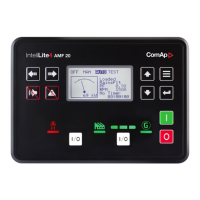
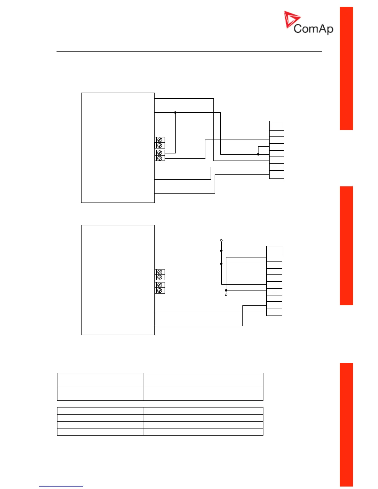
Engines started via CAN bus
VOLVO PENTA engines (EMS I, EMS II, EDC III units)
8
7
6
5
4
3
2
1
8-pin
Deutsch
connector
-
POWER D+
+
IL-MRS15/16
BINARY BO2
OUTPUTS (FUEL)
BO1
(ECU CommOK)
EXTENSION L
MODULE COM
H
SCANIA S6
1
2
3
4
5
6
7
8
9
+24 V DC
10-pin
EMS B1
connector
GND
-
POWER D+
+
IL-MRS15/16
BINARY BO2
OUTPUTS (FUEL)
BO1
(ECU CommOK)
EXTENSION L
MODULE COM
H
Engines not started via CAN bus
PERKINS 2800 series
IL-CU binary output description Perkins Customer interface connector
Start output connects directly to engine starter solenoid
Fuel output 1,10,15,33,34
powers up ECU and enables the injectors
IL-CU CAN description Perkins Customer interface connector
CAN bus common Screen for the J1939 cable.
CAN bus H 31
CAN bus L 32
InteliLite – MRS10/11/15/16, SW version 2.2, ©ComAp – November 2004 41
IL-MRS-2.2.pdf
 Loading...