Sensor specification
To correct measuring error of each analog input (pressure, temperature, level) calibrating constants
within 10 % of measure range should be set. Three calibrating constants are set in physical units - bar,
o
C, % . From these constants are counted equivalent calibrating resistance which are internally (in
software) add to sensor resistance.
At the moment of calibration (ENTER pressing) is calculated (and in memory saved) calibrating
resistance (in Ω). This value is added to measured sensor resistance before calculation of the AI1
(AI2) value.
Example: iL-CU display Temperature 70 °C and real value is 73 °C.
After setting Calibr AI1 to +3 °C (and pressing ENTER) InteliLite calculates corresponding resistance
(e.g.5Ω) and saves this value into the memory. The resistance is then added to all calculations (e.g.
instead of 70°C -> 73°C, or e.g. instead of 5°C -> 6°C).
Note:
The calibration must be done at the operational point of the analog input (e.g. 80°C, 4.0Bar etc..)
Default sensor settings
Analog input 1: 6 points VDO characteristic, pressure measuring in bar
Analog input 2: 10 points VDO characteristic, temperature measuring in °C
Analog input 3: 2 points VDO fuel level sensor, 0% = 10Ω, 100% = 180Ω
For VDO sensor characteristic see chapter Value and set points codes.
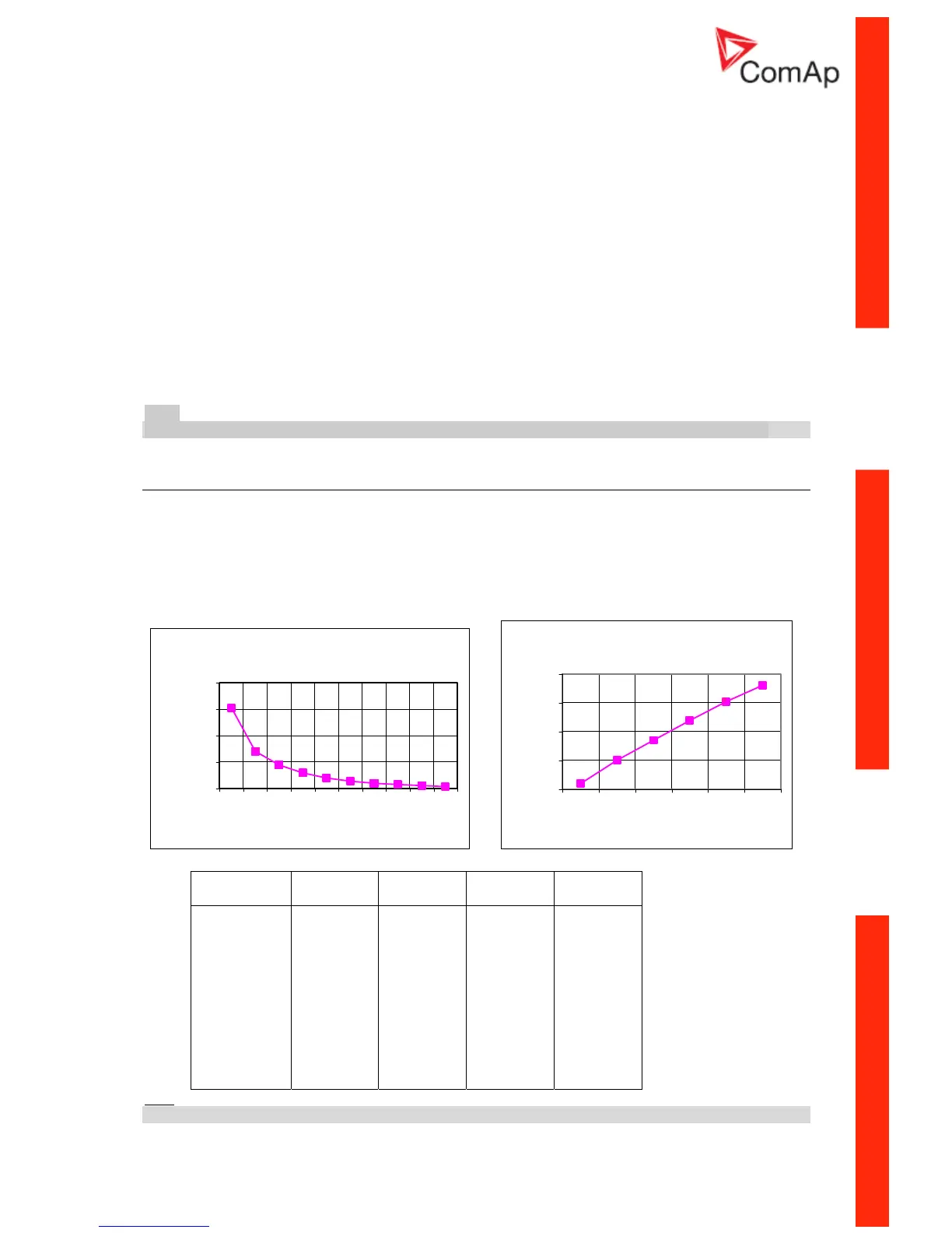
VDO Temperature sensor
0
500
1000
1500
2000
0 2030405060708090110
Temperature [ C]
Resistance [ohm]
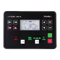
VDO Pressure sensor
0
50
100
150
200
0246810
Pressure [bar]
Resistance [ohm]
Temperature
ºC
Pt 1000
ohm
Ni 1000
ohm
-20
-10
0
30
60
80
90
100
110
120
0
922
961
1000
1117
1232
1309
1347
1385
1423
1461
-1
893
946
1000
1171
1353
1483
1549
1618
1688
1760
-1
Hint:
When measured value is 6% out of range the Sensor fail FLS is detected.
InteliLite – MRS10/11/15/16, SW version 2.2, ©ComAp – November 2004 43
IL-MRS-2.2.pdf
 Loading...