Daikin IM 972-1 13
Electrical Installation
Hook-Up
To wire unit, refer to Figure 24, page 28 for location of
wiring entrances. Wiring to be done in the field between
the unit and devices not attached to the unit, or between
separate devices which are field installed and located,
shall conform with the temperature limitation for Type
T wire [63°F rise (35°C)] when installed in accordance
with the manufacturer's instructions.
Internal Wiring
A diagram of the internal wiring of this unit is located on the
inside of control access panel and in this manual. If any of the
original wire as supplied with the unit must be replaced, the
wire gauge and insulation must be same as original wiring.
208 Volt Applications
Transformer is factory wired for 230 volts on 208/230 volt
models and must be changed for 208 volt applications. See
unit wiring diagram for 208 volt wiring.
Customer Supplied Thermostat
The customer supplied room thermostat must be compatible
with the spark ignition control on the unit. Generally, all
thermostats that are not of the “current robbing” type are
compatible with the integrated furnace control. The low
voltage wiring should be sized as shown in Table 7.
Table 7: Field Wire Size for 24 Volt Thermostat
Note: (1) The total wire length is the distance from the furnace to the
thermostat and back to the furnace. DO NOT USE CONTROL
WIRING SMALLER THAN NO. 18 AWG.
Note: DO NOT USE CONTROL WIRING SMALLER THAN NO. 18 AWG.
Install the room thermostat in accordance with the instruction
sheet packed in the box with the thermostat.
See Figure 15, page 15 for an example of a typical customer
supplied wiring diagram.
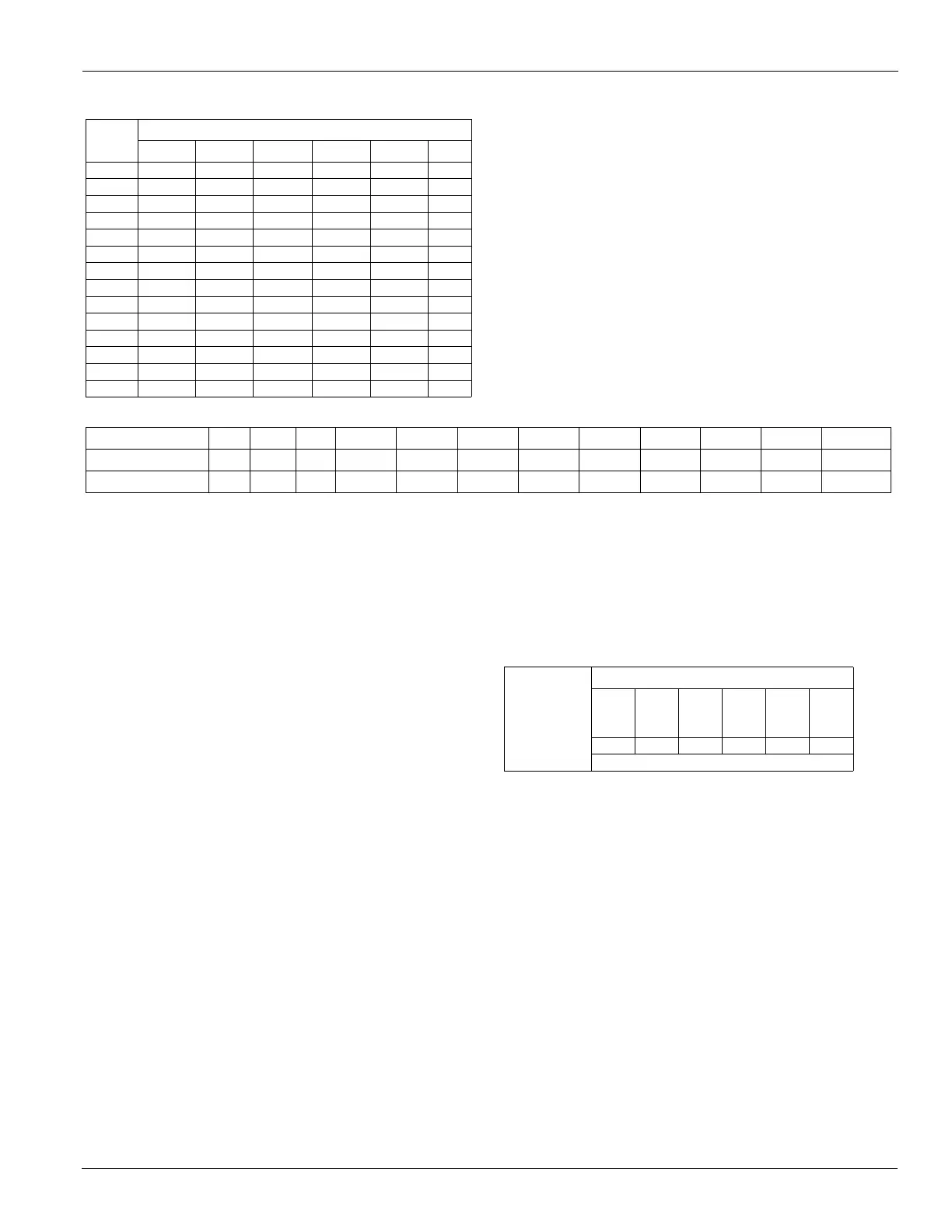
Table 5: Minimum Wire Sizes For Given Wire Length
Unit
MCA
Supply Wire Length in Feet
50 10 0 150 200 250 300
20 10 8 6 4 4 4
25 10 8 6 4 4 3
30 8 6 4 4 3 2
35 8 6 4 3 2 1
40 8 6 4 3 2 1
45 8 4 3 2 1 1/0
50 6 4 3 2 1 1/0
60 6 4 2 1 1/0 2/0
70 4 3 2 1/0 2/0 3/0
80 4 3 1 1/0 2/0 3/0
90 3 2 1/0 2/0 3/0 4/0
100 3 2 1/0 2/0 3/0 4/0
110 2 1 2/0 3/0 4/0 250
125 1 1 2/0 3/0 4/0 25
Table 6: Recommended Wire Sizes For Given Conduit and Hole Size
Wire Size, AWG 14 12 10 8 6 4 3 2 1 0 00 000
Conduit Size
1/2” 1/2” 1/2” 3/4” 1” 1” 1-1/4” 1-1/4” 1-1/2” 1-1/2” 2” 2”
Hole Size
7/8” 7/8” 7/8” 1-31/32” 1-23/64” 1-23/64” 1-23/32” 1-23/32” 1-31/32” 1-31/32” 2-15/32” 2-15/32”
Thermostat
Load Amps
Solid Copper Wire, AWG
3.0
2.5
2.0
16
16
18
14
14
16
12
12
14
10
12
12
10
10
12
10
10
10
50 100 150 200 250 300
Length of Run -Feet (1)
 Loading...