4 McQuay OM 1077
Introduction
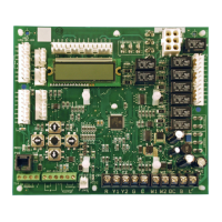
Communication module translates input and output variables
between the DDC Controller protocol and the Lon Talk
protocol. The Lon Talk Communication Module has been
developed to communicate with building automation systems
that support the Lon Mark Space Comfort Controller (SCC).
The LonMark Communication Module utilizes an FTT-10A
free topology transceiver communicating at 78.8 kbps. It is
compatible with Echelon qualified twisted pair cable, Belden
8471 or NEMA Level 4 cables. The Module can communicate
up to 1640 ft. with no repeater. The LonWorks limit of 64
nodes per segment applies to this device.
See IM 999 for full documentation
Programmable 24 Volt Thermostat
The Maverick with integral DDC Controller is compatible
with programmable 24 volt thermostats. The programmable
thermostat can supply the time schedule functions when the
DDC controller is not connected to a BAS system.
Connections are made via conventional thermostat connection
screw terminals on terminal T81. Extensive unit status and
diagnostics are displayed on the LCD screen.
Zone sensor with time clock
The Maverick I with integral DDC Controller is compatible
with a zone sensor and mechanical or solid state time clock.
The DDC Controller in each Maverick I 3 to 25 ton Package
Air Conditioner has many design features that optimize
operation, installation and service. Each unit with the DDC
Controller has the following features:
Blower On/Off Delay. Adjustable time delay between blower
on and off mode
Built-in Control Parameter Defaults. No programming
required.
Compressor Time-off Delay. Adjustable time delay between
compressor shutoff and start up
Dirty Filter Switch Input. The DDC Controller will signal an
increase in static pressure across the air filter, indicating a dirty
filter condition.
On Board User Interface Display/Keypad. Displays control
parameters, diagnostic codes, and sensor readings. The keypad
allows scrolling through display menu and field configurable
changes to be made.
Economizer Control. The economizer is controlled by the
Economizer Logic Module (ELM) that comes with the
economizer. The DDC Controller communicates with the ELM
for control, setpoint, and diagnostics. The DDC Controller has
several choices for controlling the economizer. See
Economizer Menu Screen. The ELM monitors the mixed air
temperature, return air enthalpy (optional), minimum position
set point (local or remote), power exhaust set point, CO2 set
point, CO2, and outdoor enthalpy sensor, if selected, to control
dampers to an accuracy of ±5% of stroke. The actuator is
spring returned to the closed position any time that power is
lost to the unit. It is capable of delivering up to 44 inch pounds
of torque and is powered by 24VAC.
Unit Diagnostics. The DDC Controller monitors all sensors
and functions related to unit operation to provide critical
information and maintain diagnostic code information even if
a power failure occurs.
Exhaust Fan Control Modes. Exhaust fans are controlled by
fresh air damper position. Setpoint is adjustable through the
unit display and keypad.
Field Changeable Control Parameters. Over 50 different
control parameters allow customization of the unit operation
by changing delays, cooling stages, dead bands, and set points.
Minimum Compressor Run Time. Ensures proper oil return
to the compressor.
Comfort Alert. The DDC Controller has two inputs to monitor
optional Copeland Comfort Alerts. The inputs can provide the
following information: Locked rotor, Open Circuits, Missing
Phase, Reverse Phase, and Welded Contactor.
Smoke Alarm Mode. The input will shutdown the unit and
requires a manual reset. The sensor is used to detect smoke due
to fire in the air conditioning or ventilation ducts.
Lead Lag Compressor Operation. Stage 1 compressor
operation based on compressor accumulated run time.
Staging. Depending on the unit controls up to 2 stages of
cooling, 2 stages of gas heat, and 2 stages of electric heat.
Active Protection. Provides active unit protection when any
of the following occurs three times within a thermostat cycle:
low pressure trip, high pressure trip, gas heat limit trip.
Thermostat Bounce Delay. Protects compressor from short
cycling when mechanical thermostat is used
Warm-up Mode Delay. Adjustable time that the economizer
dampers are kept in the closed position during morning warm-
up input
 Loading...


