McQuay OM 1077 9
Unit Installation
Unit Installation
Important - The DDC Controller is shipped with the control
disabled so units do not accidentally energize during
installation. The commissioning of the rooftop unit therefore
requires the configuration of the Occupied Mode menu prior to
initial startup. See Effective Occupancy‚ page 17.
The unit DDC Controller must have a thermostat or zone
sensor input in order to operate the unit. If the zone sensor is
not present, or has failed, the unit will use the return air
temperature sensor to maintain the occupied setpoint. The
flexibility of the unit mode capabilities depends upon the type
of zone sensor or thermostat selected to interface with the
DDC controller.
The descriptions of the following basic Input Devices used
within the DDC controller network are to acquaint the operator
with their function as they interface with the various modules.
Refer to the unit's electrical schematic for the specific module
connection.
The following controls are available from the factory for field
installation:
Controls using 24 VAC
Before installing any connecting wiring, refer to the unit
installation manual for AC conductor sizing guidelines “Field
Wire Size For 24 Volt Thermostat Circuits”, for the electrical
access locations provided on the unit, and;
• Use copper conductors unless otherwise specified.
• Ensure that the AC control wiring between the controls and
the unit's termination point does not exceed three (3) ohms
per conductor for the length of the run.
Note: Resistance in excess of 3 ohms per conductor may
cause component failure due to insufficient AC voltage
supply.
• Be sure to check all loads and conductors for grounds,
shorts, and mis-wirings.
• Do not run the AC low voltage wiring in the same conduit
with the high voltage power wiring.
• Some thermostat wire insulation has a voltage rating less
than the line voltage. Route Thermostat Wire behind low
voltage shield during unit installation per Figure 2. This is
necessary to meet National Electrical Code (NEC) and UL
1995 requirements for separation of high and low voltage
circuits.
Controls using DC Analog Input/Outputs (Standard
Low Voltage Multi-conductor Wire)
Before installing any connecting wiring between the unit and
components utilizing a DC analog input/output signal, refer to
the unit installation manual for the electrical access locations
provided on the unit.
• Use shielded cable for high EMI environments.
Note: Resistance in excess of 2.5 ohms per conductor can
cause deviations in the accuracy of the controls.
• Ensure that the wiring between controls and the unit's
termination point does not exceed two and a half (2.5) ohms
per conductor for the length of the run.
• Do not run the electrical wires transporting DC signals in or
around conduit housing high voltage wires.
• Most sensor wire insulation has a voltage rating less than the
line voltage. Route Zone Sensor and Network Cable behind
low voltage shield during unit installation per Figure 2. This
is necessary to meet NEC and UL 1995 requirements for
separation of high and low voltage circuits.
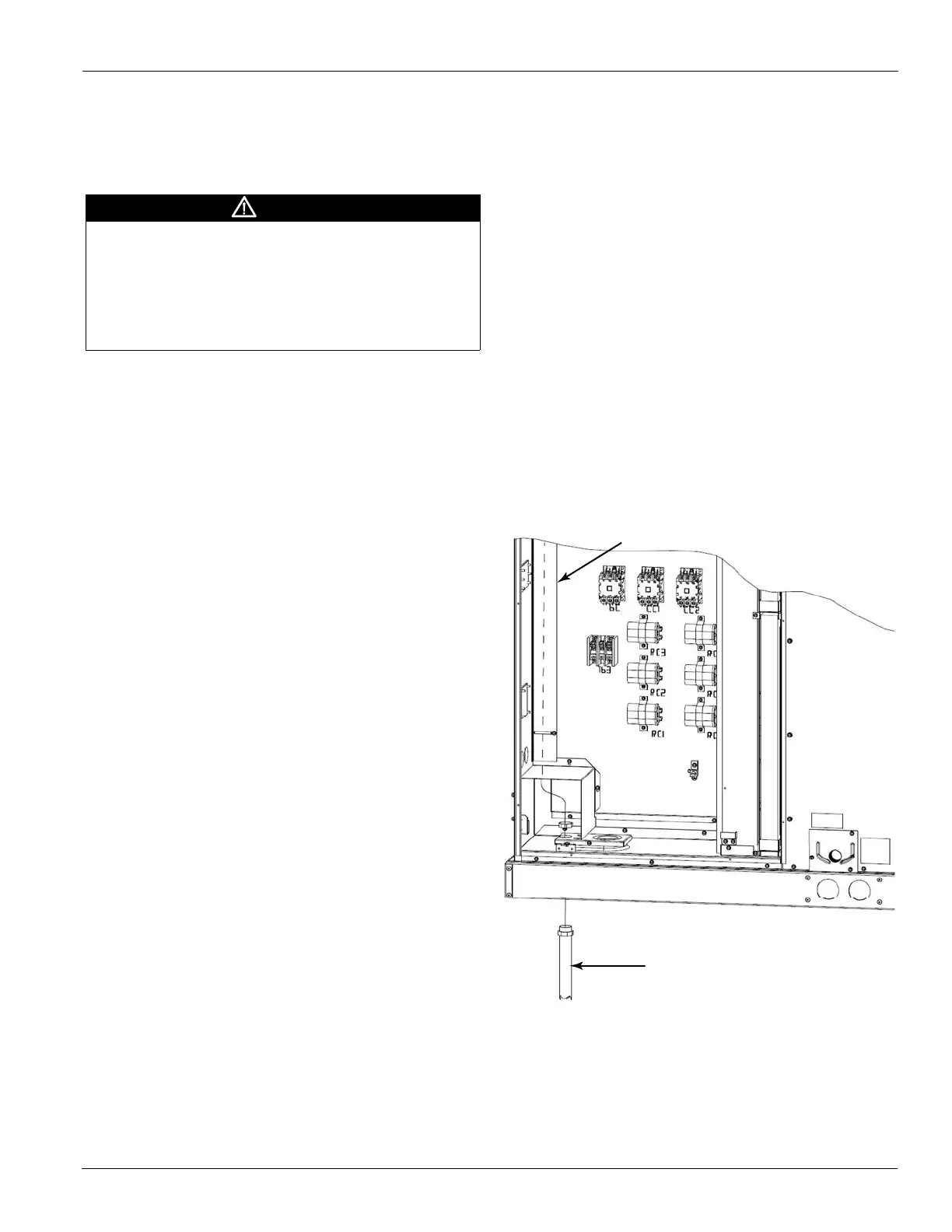
Figure 2: Low Voltage Shielding
Stand Alone with Thermostat
Once Occupied Mode is set to “Control by Thermostat” the
DDC Controller will follow the commands from a regular
24VAC thermostat, according to the following convention:
• G - Indoor fan
• Y1 - First stage of compressor
DANGER
Before beginning any modification, be sure main disconnect
switch is in the “off” position. Disconnect all electric power,
including remote disconnect before servicing. Failure to do so
can cause electrical shock resulting in property damage,
personal injury or death. Follow proper lockout/tag out
procedures to ensure the power cannot be inadvertently
energized.
Conduit for Low
Voltage Conductors
Sheilding for Low
Voltage Conductors
 Loading...