Control Specification SiE12-411
104 Function and Control
Checking the
current setting
data on the
microcomputer
memory
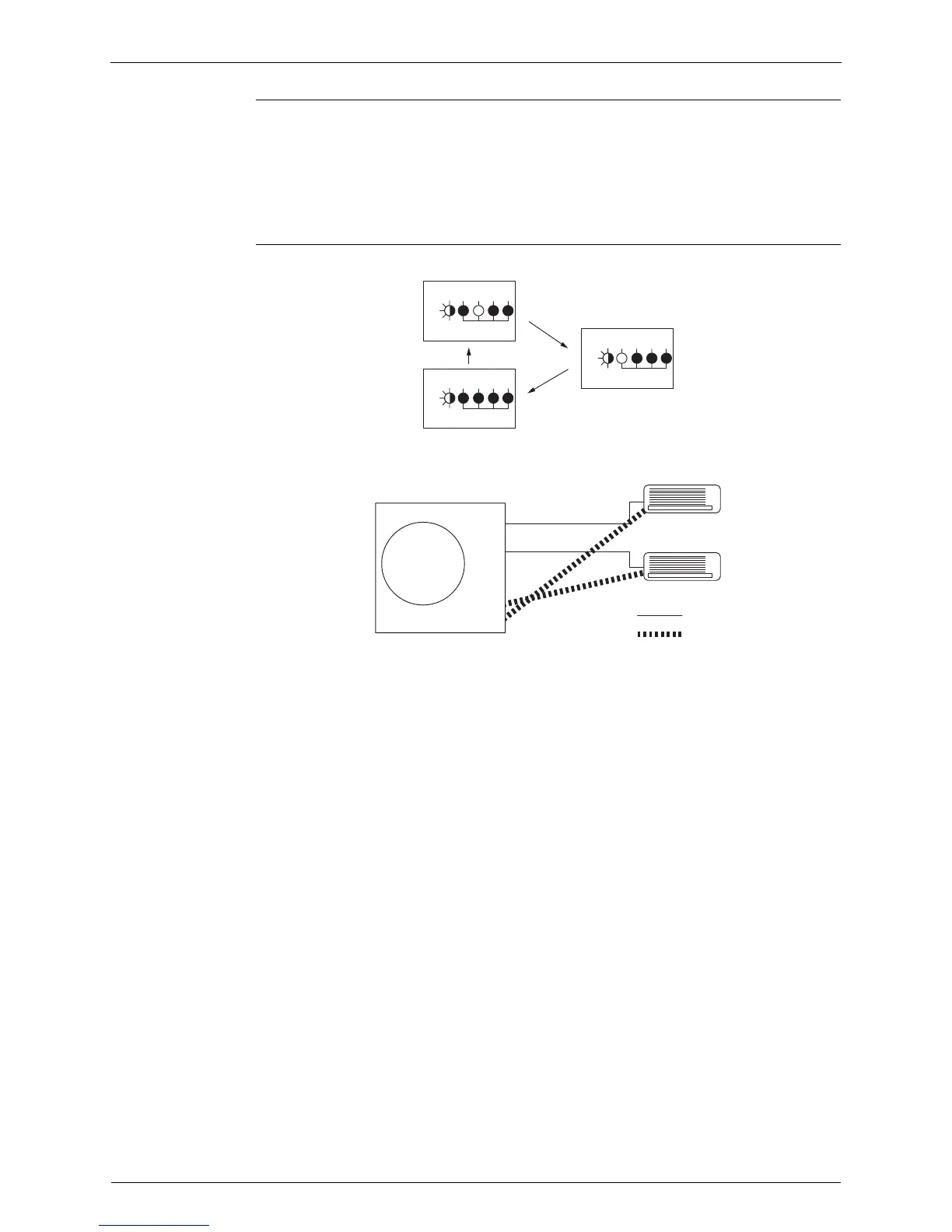
Those data can be checked by looking at the service monitor LED indicators, when the wiring
error checking is over, during forced operation, at the stop of the system.
The LED indicators stop flashing when the forced operation is over.
LED1…Room A wiring, LED2…Room B wiring
1st flashing LED…Port A piping, 2nd flashing LED…Port B piping
The first stay-on LED means the room that is connected with Port A. The next stay-on LED
means the one connected with Port B.
Example Let's suppose the LED indicators are flashing as follows.
The above means that Port A is connected with Port B and Port B with Room A (or self-
corrected this way.)
A 1 2 3 4
Green Red
Green Red
Green Red
A 1 2 3 4
A 1 2 3 4
L
E
D
L
E
D
L
E
D
Wiring
Piping
Wiring
Piping
A
B
A
B
 Loading...