Printed Circuit Board Connector Wiring Diagram SiE12-411
66 Printed Circuit Board Connector Wiring Diagram
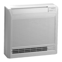
1.5 Floor Standing Type
Connectors
Note: Other Designations
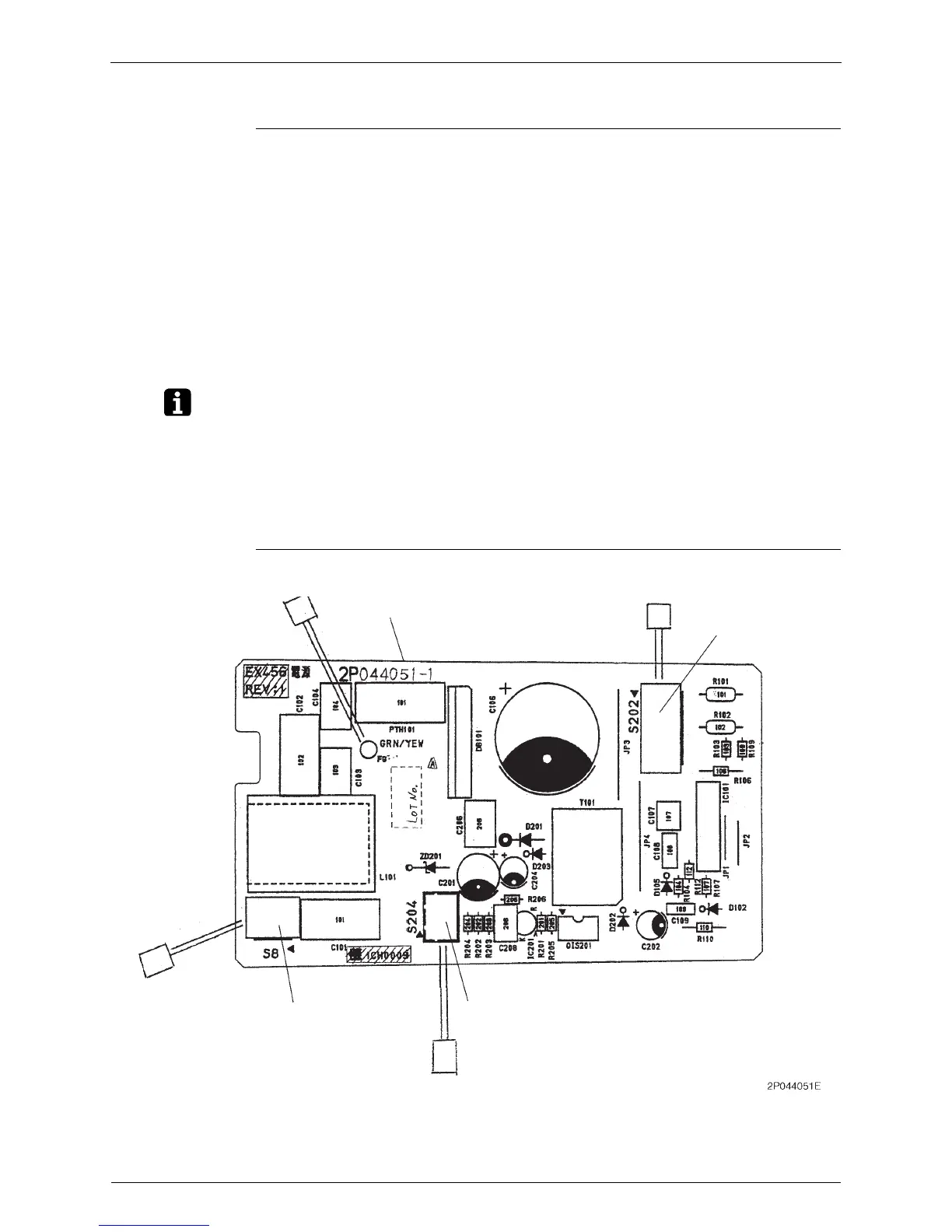
Power Supply PCB (PCB 1)
1) S6 Connector for swing motor and lower air outlet motor
2) S21 Connector for HA
3) S23 Connector for signal receiver
4) S31, S32 Connector for room temperature / heat exchanger thermistor
5) S201, S203,
S7, S24, S26
Connector for power supply PCB (1)
6) S202, S204,
S8
Connector for control PCB (2)
7) S25 Connector for display PCB (3)
8) S301, S302 Connector for fan motors
1) V1 Varistor
2) FU Fuse
3) LED11 LED for operation
4) LED12 LED for timer
5) LED14 LED for HOME LEAVE operation
S8
S204
S202
PCB1
 Loading...