Manual Displacement Control (MDC)
MDC principle
An MDC is a Manual proportional Displacement Control (MDC). The MDC consists of a handle on top of a
rotary input shaft. The shaft provides an eccentric connection to a feedback link. This link is connected on
its one end with a porting spool. On its other end the link is connected the pumps swashplate.
This design provides a travel feedback without spring. When turning the shaft the spool moves thus
providing hydraulic pressure to either side of a double acting servo piston of the pump.
Differential pressure across the servo piston rotates the swash plate, changing the pump’s displacement.
Simultaneously the swashplate movement is fed back to the control spool providing proportionality
between shaft rotation on the control and swashplate rotation.
The MDC changes the pump displacement between no flow and full flow into opposite directions. Under
some circumstances, such as contamination, the control spool could stick and cause the pump to stay at
some displacement.
A serviceable 125 μm screen is located in the supply line immediately before the control porting spool.
The MDC is sealed by means of a static O-ring between the actuation system and the control block. Its
shaft is sealed by means of a special O-ring which is applied for low friction. The special O-ring is
protected from dust, water and aggressive liquids or gases by means of a special lip seal.
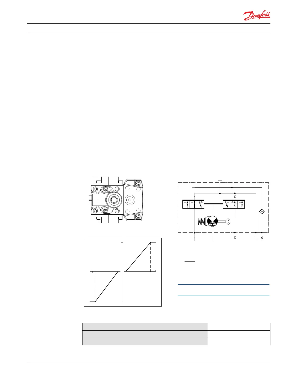
Manual Displacement Control on H1 pump
Pump displacement vs. control lever rotation
"0"
Lever rotation
"A"
Displacement
100 %
a
-a
100 %
"B"
-b
-d
b
c
d
-c
MDC schematic diagram
Where:
Deadband on B side – a = 3° ±1°
Maximum pump stroke – b = 30° +2/-1°
Required customer end stop – c = 36° ±3°
Internal end stop – d = 40°
Volumetric efficiencies of the system will have impacts on
the start and end input commands.
MDC torque
Torque required to move handle to maximum displacement
1.4 N•m [12.39 lbf•in ]
Torque required to hold handle at given displacement
0.6 N•m [5.31 lbf•in]
Maximum allowable input torque
20 N•m [177 lbf•in]
Technical Information H1 Axial Piston Single Pumps, Size 069/078
Control options
11062169 • Rev 0700 • November 2015 19
 Loading...