MDC general information
In difference to other controls the MDC provides a mechanical deadband. This is required to overcome
the tolerances in the mechanical actuation.
The MDC contains an internal end stop to prevent over travel. The restoring moment is appropriate for
turning the MDC input shaft back to neutral only. Any linkages or cables may prevent the MDC from
returning to neutral.
The MDC is designed for a maximum case pressure of 5 bar and a rated case pressure of 3 bar. If the case
pressure exceeds 5 bar there is a risk of an insufficient restoring moment. In addition a high case pressure
can cause the NSS to indicate that the control is not in neutral. High case pressure may cause excessive
wear.
Customers can apply their own handle design but they must care about a robust clamping connection
between their handle and the control shaft and avoid overload of the shaft.
Customers can connect two MDC’s on a tandem unit in such a way that the actuation force will be
transferred from the pilot control to the second control but the kinematic of the linkages must ensure
that either control shaft is protected from torque overload.
To avoid an overload of the MDC, customers must install any support to limit the setting range of the
Bowden cable.
Caution
Using the internal spring force on the input shaft is not an appropriate way to return the customer
connection linkage to neutral.
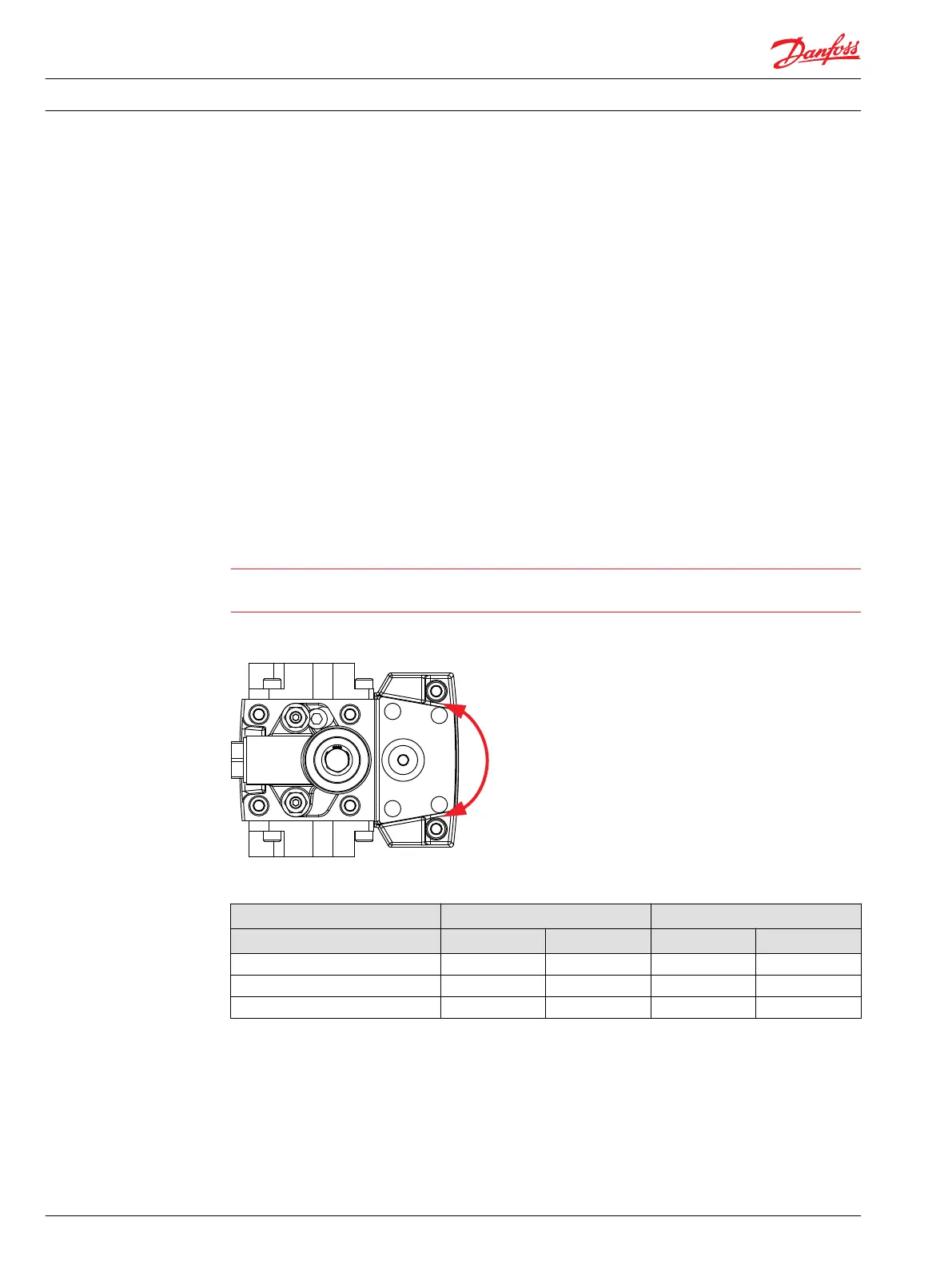
Shaft rotation MDC
MDC shaft rotation data
Pump shaft rotation
*
Clock Wise (CW) Counter Clock Wise (CCW)
MDC shaft rotation CW CCW CW CCW
Port A in (low) out (high) out (high) in (low)
Port B out (high) in (low) in (low) out (high)
Servo port high pressure M5 M4 M5 M4
*
As seen from shaft side.
Control response
H1 controls are available with optional control passage orifices to assist in matching the rate of
swashplate response to the application requirements (e.g. in the event of electrical failure). The time
required for the pump output flow to change from zero to full flow (acceleration) or full flow to zero
(deceleration) is a net function of spool porting, orifices, and charge pressure. A swashplate response
table is available for each frame indicating available swashplate response times. Testing should be
conducted to verify the proper orifice selection for the desired response.
Technical Information
H1 Axial Piston Single Pumps, Size 069/078
Control options
20 11062169 • Rev 0700 • November 2015
 Loading...