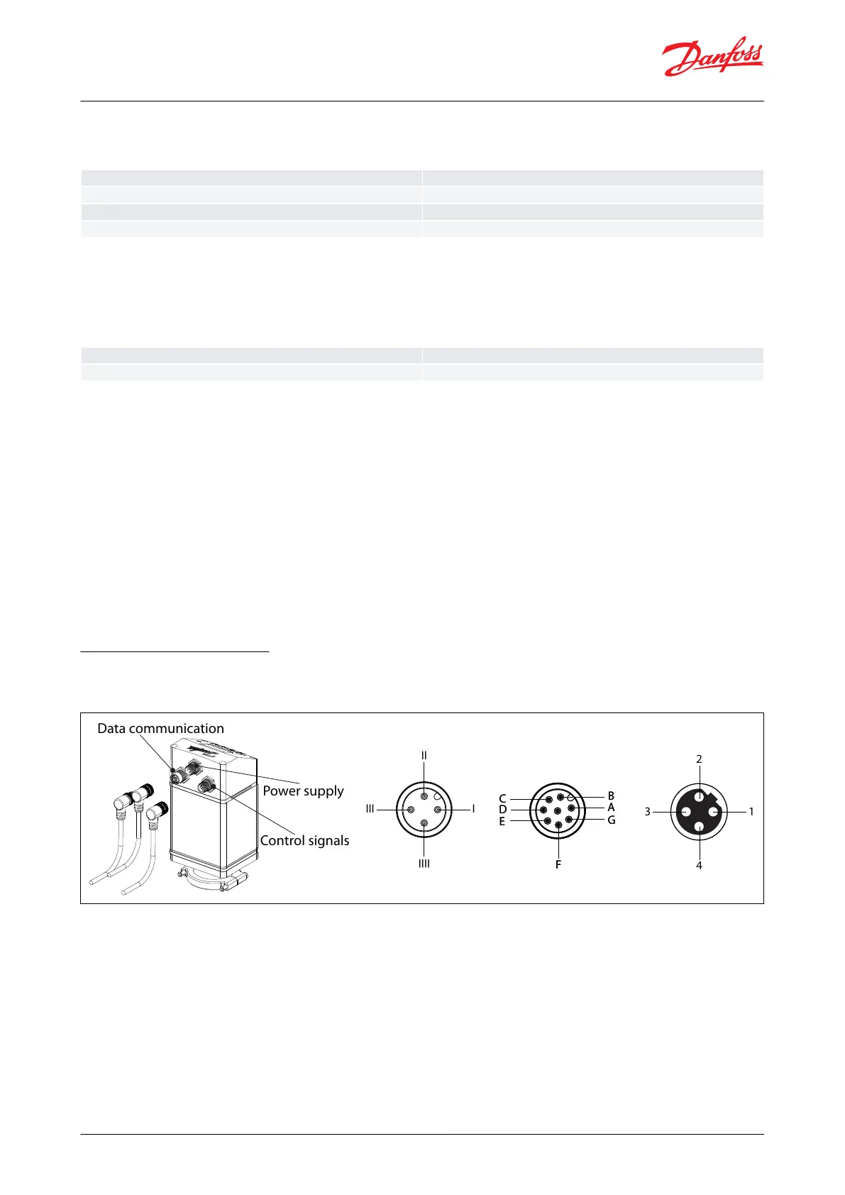
Figure 6: Cable Connectors
III
I
II
IIII
CC
DD
EE
BB
AA
GG
FF
2
4
13
Data communication
Power supply
Control signals
Analog Output
Table 7: Current
Recommended external resistor for Hot application
Rext=800 Ω-load 1W power rate
Digital Input
Digital ON/OFF input by means of voltfree contact (Signal/Telecom relays with gold-plated contacts recommended)
– Voltage input used.
Table 8: Current
Digital Output
Digital Output - 3 pcs. NPN transistor output.
External supply
7 – 24 V DC (same supply as for ICAD can be used, but please note that the galvanically isolated system will then be
spoiled).
On resistance
55 Ω + diode voltage 0.7 V DC
Max 70 Ω at 50 mA
Max Output current: 50 mA
Reverse polarity protection: Yes
Overcurrent protection: No
Wiring the ICAD actuator
There are three cables which are connected to the ICAD motor with M12 connectors:
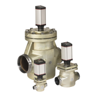
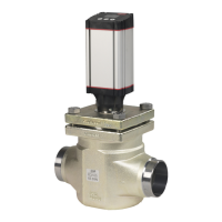
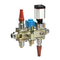
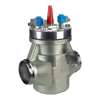
ICM and ICMTS Motorized Valves with ICAD Actuators
© Danfoss | Climate Solutions | 2024.01 BC465027827472en-000102 | 10
 Loading...