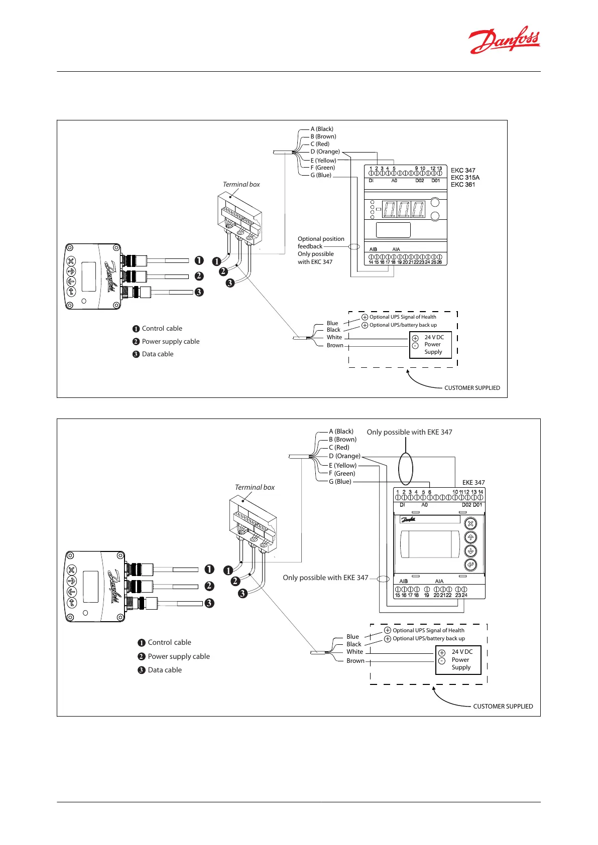
Figure 9: ICAD wired to a Danfoss EKC controller - Analog I/O for modulating control
White
Brown
24 V DC
Power
Supply
Black
Blue
+
-
Optional UPS/battery back up
Optional UPS Signal of Health
+
+
CUSTOMER SUPPLIED
Control
Power supply cable
cable
Terminal box
2
1
3
Data cable
2
1
3
2
3
Optional position
feedback
Only possible
with EKC 347
A (Black)
B (Brown)
C (Red)
D (Orange)
E (Yellow)
F
(Green)
G (Blue)
Wiring diagram showing ICAD wired to a Danfoss EKC/EKE controller
Figure 10: ICAD wired to a Danfoss EKE controller - Digital I/O for ON/OFF valve operation
White
Brown
24 V DC
Power
Supply
Black
Blue
+
-
Optional UPS/battery back up
Optional UPS Signal of Health
+
+
CUSTOMER SUPPLIED
Control
Power supply cable
cable
Terminal box
2
1
3
Data cable
2
1
3
2
3
A (Black)
B (Brown)
C (Red)
D (Orange)
E (Yellow)
F
(Green)
G (Blue)
EKE 347
Only possible with EKE 347
Only possible with EKE 347
NOTE:
For instructions on completely wiring an EKE controller, please see the relevant EKE controller manual.
ICM and ICMTS Motorized Valves with ICAD Actuators
© Danfoss | Climate Solutions | 2024.01 BC465027827472en-000102 | 12
 Loading...