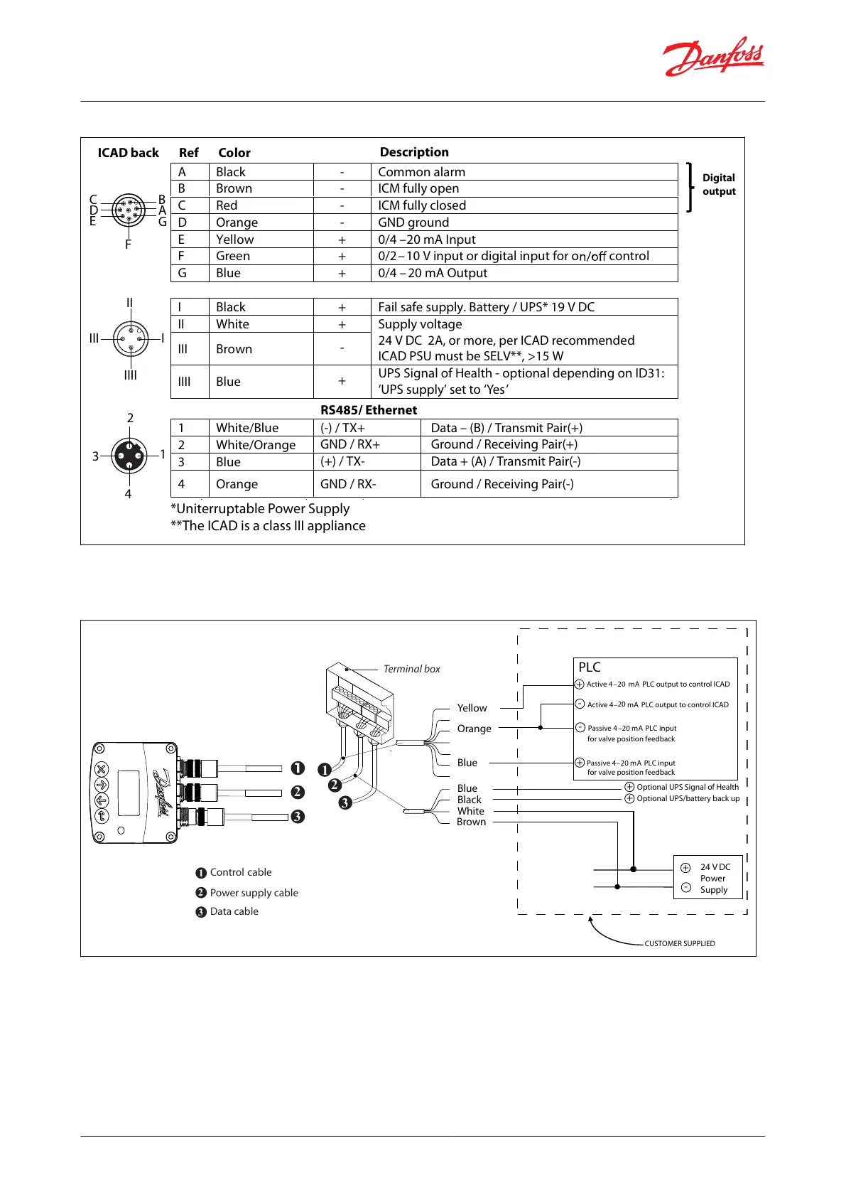
Figure 7: ICAD back Description
A Black - Common alarm
B Brown - ICM fully open
C Red - ICM fully closed
D Orange - GND ground
E Yellow + 0/4 –20 mA Input
F Green + 0/2–10 V input or digital input for o control
G Blue + 0/4 – 20 mA Output
I Black + Fail safe supply. Battery / UPS* 19 V DC
II White + Supply voltage
24 V DC 2A, or more, per ICAD recommended
ICAD PSU must be SELV**, >15 W
III Brown
-
IIII Blue
+
UPS Signal of Health - optional depending on ID31:
‘UPS supply’ set to ‘Yes’
Digital
output
1 White/Blue
2 White/Orange
3 Blue
4 Orange
(-) / TX+ Data – (B) / Transmit Pair(+)
GND / RX+ Ground / Receiving Pair(+)
(+) / TX- Data + (A) / Transmit Pair(-)
GND / RX- Ground / Receiving Pair(-)
ICAD back Ref Color
Description
RS485/ Ethernet
III I
II
IIII
C
D
E
B
A
G
F
2
4
1
3
*Uniterruptable Power Supply
**The ICAD is a class III appliance
Wiring diagram showing ICAD wired to a PLC or other type of third party electronics
Figure 8: ICAD wired to a PLC
24 V DC
Power
Supply
CUSTOMER SUPPLIED
White
Brown
Yellow
Orange
PLC
Blue
Blue
Active 4–
20
mA PLC output to control ICAD
Passive 4 –20 mA PLC input
for valve position feedback
Passive 4–20 mA PLC input
for valve position feedback
Black
Optional UPS/battery back up
Optional UPS Signal of Health
Active 4–20 mA PLC output to control ICAD
+
+
+
+
-
-
+
-
Control
Power supply cable
cable
Terminal box
2
1
3
Data cable
2
1
3
2
3
NOTE:
Note: The ICAD supplies the power for the 4–20 mA feedback signal.
© Danfoss | Climate Solutions | 2024.01 BC465027827472en-000102 | 11
ICM and ICMTS Motorized Valves with ICAD Actuators
 Loading...