Troubleshooting
Overview
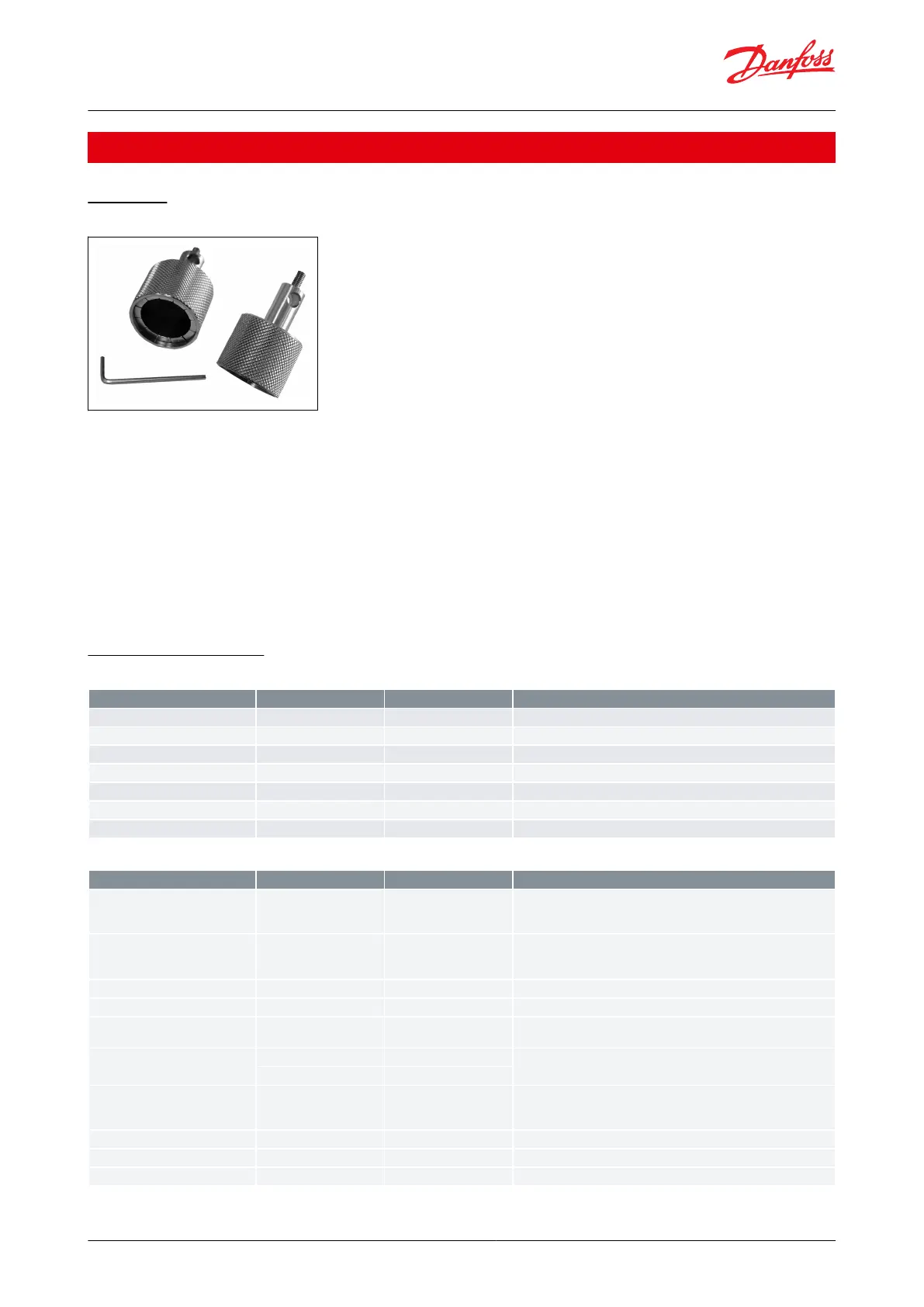
Figure 17: Manual tool
The ICAD actuator has a number of very useful service parameters which should always be consulted rst. In
addition, a manual tool should always be available to manually close the valve completely in the event the ICAD has
failed. When using the manual tool, turn the tool clockwise to open the valve and counterclockwise to close the
valve.
NOTE:
When rotating the valve manually you are changing the position of the valve to a value dierent than what is in the
actuator’s memory. Therefore, a calibration must be performed when ICAD is remounted to the valve. If power is cut
from the actuator prior to using the manual tool or after the valve has been adjusted, no problem will occur as the
valve will automatically recalibrate itself once power is restored. Power can easily be disconnected and reconnected
by unscrewing and then reconnecting the power cable from the ICAD actuator.
Warnings and Alarms
Table 9: Warnings - Flashing yellow
At start-up A1 will be displayed
State of health for UPS battery
Bluetooth connection issue
Supply voltage higher then 24V DC +10%
Supply voltage lower then 24V DC -15%
Table 10: Alarms - Flashing red
Internal fault inside electronics. Carry out: 1) Power OFF and Power ON
If A2 still active. 2) Make a Reset to factory setting If A2 still active. Re-
turn ICAD to Danfoss
Not active if ID2 = 2, or ID3 = 4 When ID3 = 0 and AI A > 22 mA When
ID3 = 1 and AI A > 22 mA or AI A < 2 mA When ID3 = 2 and AI A > 12 V
When ID3 = 3 and AI A > 12 V or AI A < 1 V
Low voltage of fail safe Supply
If 5 V < fail safe supply
Calibration extended failed
Check valve type selected. Check presence of foreign body internally
in valve
Internal temperature alarm
Temperature for stepper motor component too high. Ventilate/lower
ambient ICAD temperature
POM mode (Preventive Operational
Mode)
If ICAD meets too high torque from ICM valve (increased friction/stick-
ing surfaces) ICAD automatic goes into POM mode to overcome lost
step.
Update of the software failed
Valve size detection fail
ICM and ICMTS Motorized Valves with ICAD Actuators
© Danfoss | Climate Solutions | 2024.01 BC465027827472en-000102 | 38
 Loading...