The pump outlet feeds directional control valves such as PVG-32, hydraulic integrated circuits (HIC), and
other types of control valves.
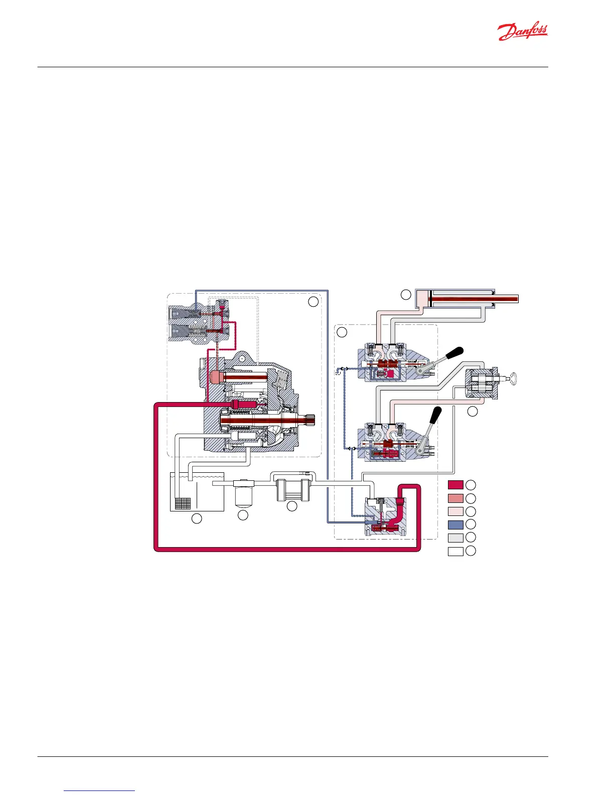
The PVG valve directs and controls pump flow to cylinders, motors and other work functions. A heat
exchanger cools the fluid returning from the valve. A filter cleans the fluid before it returns to the
reservoir.
Flow in the circuit determines the speed of the actuators. The position of the PVG valve spool determines
the flow demand. A hydraulic pressure signal (LS signal) communicates demand to the pump control.
The pump control monitors the pressure differential between pump outlet and the LS signal, and
regulates servo pressure to control the swashplate angle. Swashplate angle determines pump flow.
Actuator load determines system pressure. The pump control monitors system pressure and will decrease
the swashplate angle to reduce flow if system pressure reaches the pump control setting.
A secondary system relief valve in the PVG valve acts as a back-up to control system pressure.
Pictorial circuit diagram
 Loading...