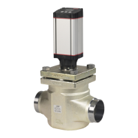
PVH, hydraulic actuation
Technical data for PVH
Control range pressure
5 – 15 bar [75 – 220 psi]
Max. pilot pressure
30 bar [435 psi]
Max. pressure on port T (the hydraulic remote control lever should be
connected directly to tank.)
10 bar [145 psi]
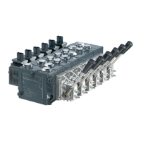
PVM, mechanical actuation
Operating torque for PVM
Spool displacement Operating torque N•m [lbf•in]
PVM + PVMD PVM + PVE PVM + PVH PVM + PVMR PVM+PVMF
from neutral position 2.2 ±0.2
[19.5 ±1.8]
2.2 ±0.2
[19.5 ±1.8]
2.5 ±0.2
[22.1 ±1.8]
17
[3.8]
22
[5.0]
max. spool travel 2.8 ±0.2
[24.8 ±1.8]
2.8 ±0.2
[24.8 ±1.8]
6.9 ±0.2
[61.0 ±1.8]
– –
into float position – – – – 60 [13.5]
away from float position – – – – 28 [6.3]
from any other position – – – 8.5 [73.3] –
No control lever position
2 x 6
Control lever range
±19.5°
Proportional control lever range
±13.4°
Control lever range – float position
22.3°
For further information about PVE please see the Technical Information PVE, Series 4 for PVG 32/100/120 ,
520L0553.
PVE, electrical actuation
Technical data for PVEO and PVEM
Supply voltage U
DC
rated
12 V
DC
24 V
DC
range
11 V to 15 V 22 V to 30 V
max. ripple
5%
Current consumption at rated voltage
0.65 A @ 12 V 0.33 A @ 24 V
Signal voltage (PVEM) neutral
0.5 x U
DC
A-port ↔ B-port
0.25 • U
DC
to 0.75 • U
DC
Signal current at rated voltage (PVEM)
0.25 mA 0.50 mA
Input impedance in relation to 0.5 • U
DC
12 KΩ
Power consumption
8 W
Technical Information
PVG 32 Proportional Valve Group
PVG 32 technical data
26 |
©
Danfoss | August 2017 520L0344 | BC00000038en-US0802
 Loading...