PVEA, PVEH, PVES, PVEU
Variants:
•
-F for float in B-direction
max. flow B at 4.8 mm
•
-F for float in A-direction
max. flow A at 5.5 mm
•
PVES-SP with spool position feedback
•
Anodized aluminum block
•
ATEX certified
Power supply: 11→ 32 V
Connectors:
•
AMP
•
DIN/Hirshmann
•
Deutsch
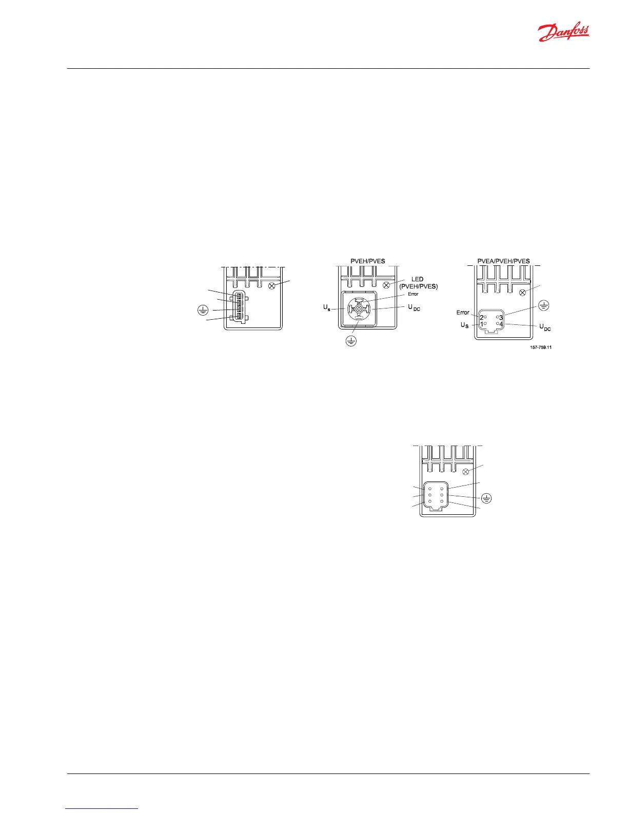
®
AMP version DIN/Hirschmann version Deutsch
®
version
PVEA, PVEH, PVES, PVEU
and PVEH float A
PVEH, PVEM, PVES,
PVEH float B and PVEM float B
PVEA, PVEH, PVES, PVEU
and PVEH float B
PVEP
The PVEP is controlled with separate PWM control signals
for A and B direction.
The PVEP has hysteresis and fault monitoring like the
PVES.
Power supply: 11→ 32 V
Connector: Deutsch
®
Deutsch
®
version
PVED-CC and PVED-CX
The CAN controlled PVE embedded microcontrollers support the same high spool controllability as the
PVES and additional has high quality feedbacks, safety monitoring and detailed diagnostics.
PVED has digital communication, that allows a wide range of feedback, setpoint and highly costumized
settings. CAN bus serial communication makes wiring much easier. Only one cable per PVG group.
Technical Information
PVG 32 Proportional Valve Group
Electrical actuation
©
Danfoss | August 2017 520L0344 | BC00000038en-US0802 | 33