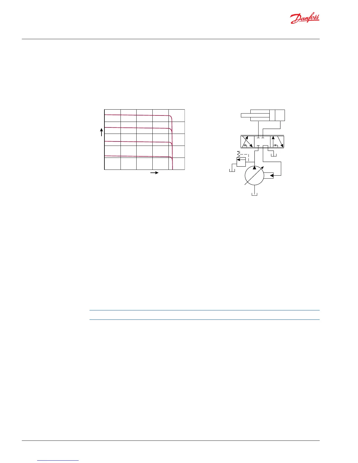
Most load sensing systems use parallel, closed center, control valves with special porting that allows the
highest work function pressure (LS signal) to feed back to the LS control.
Margin pressure is the difference between system pressure and the LS signal pressure. The LS control
monitors margin pressure to read system demand. A drop in margin pressure means the system needs
more flow. A rise in margin pressure tells the LS control to decrease flow.
LS control with bleed orifice (do not use with PVG valves)
The load sense signal line requires a bleed orifice to prevent high-pressure lockup of the pump control.
Most load-sensing control valves include this orifice. An optional internal bleed orifice is available, for use
with control valves that do not internally bleed the LS signal to tank.
Integral PC function
The LS control also performs as a PC control, decreasing pump flow when system pressure reaches the PC
setting. The pressure compensating function has priority over the load sensing function.
For additional system protection, install a relief valve in the pump outlet line.
Load sensing system characteristics:
•
Variable pressure and flow
•
Low pressure standby mode when flow is not needed
•
System flow adjusted to meet system requirements
•
Lower torque requirements during engine start-up
•
Single pump can supply flow and regulate pressure for multiple circuits
•
Quick response to system flow and pressure requirements
Remote pressure compensated controls
The remote PC control is a two-stage control that allows multiple PC settings. Remote PC controls are
commonly used in applications requiring low and high pressure PC operation.
Technical Information
PVG 32 Proportional Valve Group
Function
16 |
©
Danfoss | August 2017 520L0344 | BC00000038en-US0802
 Loading...