•
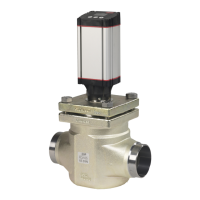
PVPE, full flow dump for the PVG 120
•
External cartridge valve connecting LS pressure to tank
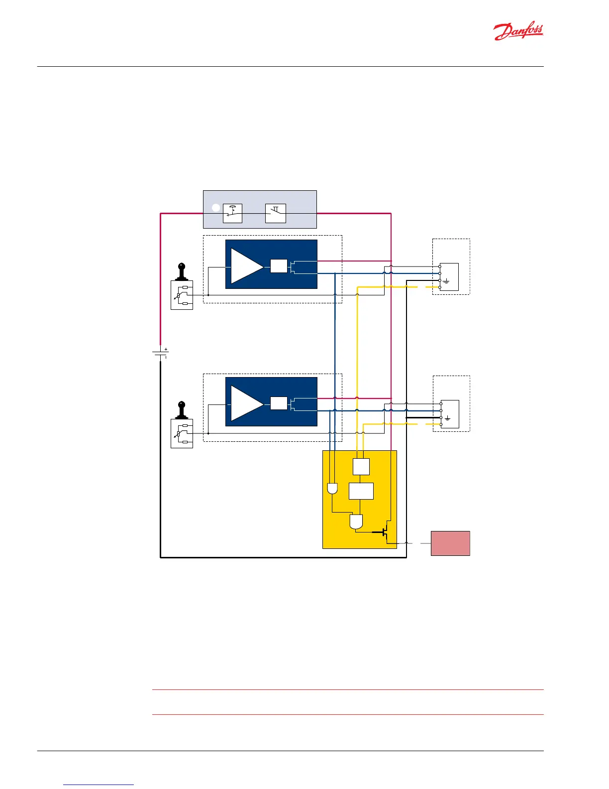
Examples of wiring block diagram
Example of a typical wiring block diagram using PVEH with neutral power off switch and fault monitoring
output for hydraulic deactivation.
Fault detection output
high=on
low=off
Alarm
logic
2)
Memory3)
E1
E2
Output
AND
OR
U
DC2
Error
U
S
Neutral detection / Supply control
signal
≠
neutral
OFF
Delay
1)
U
DC2
Error
U
S
PVEH
with AMP
connector
PVEH
with AMP
connector
Hydraulic
deactivation
Neutral detection / Supply control
signal
≠
neutral
OFF
Delay
1)
PVE 1
PVE 2
Emergency
stop
Man present
switch
C
C
D
B
B
A
P301 318
A– Emergency stop / man present switch
B– PVE Fault monitoring signals
C– Neutral signal detection.
D– Hydraulic deactivation
System Control Logic e.g. PLUS+1® for signal monitoring and triggering signal for deactivation of the
hydraulic system.
Warning
It is the responsibility of the equipment manufacturer that the control system incorporated in the
machine is declared as being in conformity with the relevant machine directives.
Technical Information
PVG 32 Proportional Valve Group
Safety in application
14 |
©
Danfoss | August 2017 520L0344 | BC00000038en-US0802
 Loading...