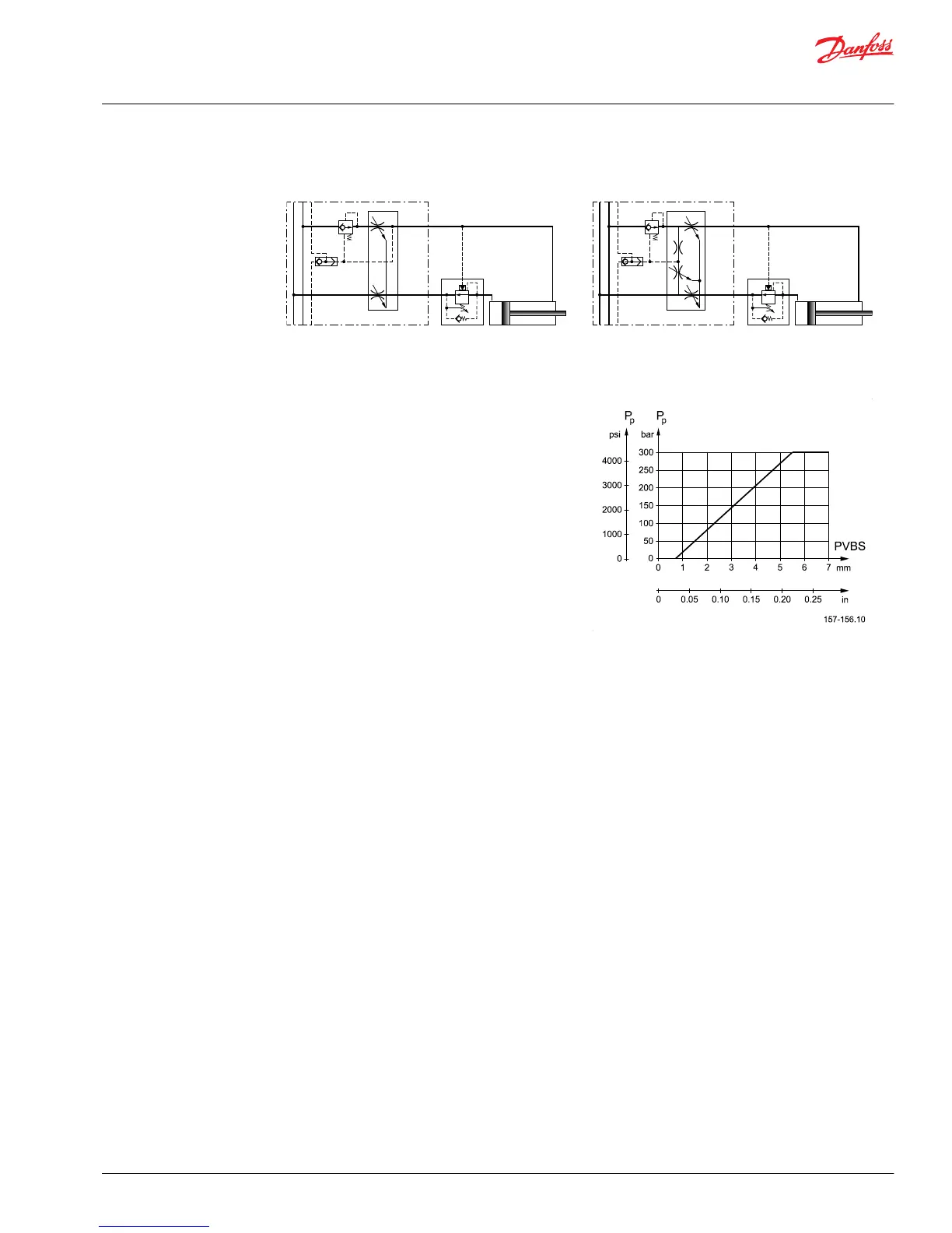
The opening area of the variable orifice is at maximum at
initial actuation and 0 at full stroke of the spool and then
the pressure created between the two orifices is led into
the LS system in the usual way.
In this way the pump pressure is built up depending on
the spool travel, e.g. the spool will then have to be
stroked to a position that the pump pressure is higher
than the actual load pressure to make the oil flow from
P➝A/B.
When the load changes for a fixed spool position the flow
to for the function will also change.
The valve section is now a load-dependent valve, but
ensuring a constant pump pressure which is important in
obtaining a stable function.
Pump pressure vs. spool travel curve
Application
Pressure controlled spools should in principle only be used when you have stability issues. Typical
applications on a crane:
•
Lifting/lowering movement
•
Slewing movement with cylinders
•
For the main lifting/lowering function on a crane it is recommended to fit a "half" pressure control
spool. This means that the spool is designed with a normal flow control on the lifting port and
pressure control connected to the port where the pilot signal to the over-center valve is acting. You
will thus maintain a load-independent lifting movement and achieve a stable but load-depending
lowering movement.
•
As the load pressure on slewing movements is usually steady - irrespective of the crane being loaded
or not – it will be advantageous to use a "full" pressure control spool for A and B port.
In both cases we recommend the use of a basic valve, PVB, with pressure compensator. The pressure
compensator will ensure the individual load-independency between the basic valves.
It is further recommended to use the LS pressure relief valves as not only will they ensure individual
pressure limitation but also make it possible to adjust the maximum oil flow to the function.
It is not recommended to use shock valves as pressure limiting valves in connection with pressure control
spools.
Sizing
The size of "half" (e.g: P - A = flow control P - B pressure control) pressure control spools is determined on
basis of max. flow demand on the lifting port. If e.g. a max. pressure compensated flow of 65 l/min for the
lifting movement, you choose a 65 L/min spool (size D). The metering characteristic has then a given size.
As it is often requested to limit the use of the crane boom for downward push/force mode and the LS
Technical Information
PVG 32 Proportional Valve Group
Function
©
Danfoss | August 2017 520L0344 | BC00000038en-US0802 | 23
 Loading...