The form can be obtained from the Danfoss Sales Organization. An order form for PVG 32 hydraulic valve
is shown on the page PVG 32 order specification.
Both the module selection chart on the previous pages and the order form are divided into fields 0,
1-1-12, 13, 14, 15, a, b, and c.
Each module has its own field:
0:
•
Pump side module PVP
•
Plug for external pilot oil supply PVPC
•
Electrical LS unloading valve PVPX
1-12: Basic valves PVB
13: Main spool PVBS
a: Mechanical actuator PVM (or PVE when option mounted)
b:
•
Shock and suction valve PVLP
•
Suction valve PVLA
c:
•
Cover for mechanical actuation PVMD
•
Cover for hydraulic actuation PVH
•
Electrical actuators PVE (or PVM when option mounted)
14: End plate PVS
15: Assembly kit PVAS
Please state:
•
Code numbers of all modules required
•
Required setting (P) for pump side module
•
Required setting of LS
A/B
pressure limiting valves, see pressure setting guidance below.
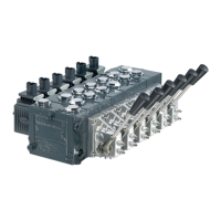
Standard and option assembly
The PVG 32 valve group is assembled the way the module selection chart shows if the code number for
PVM is written in field 'a', and the code number for PVMD, PVE or PVH in field 'c'.
The valve group is assembled so that the mechanical actuator is mounted on the opposite end of the
basic module, if the code number for PVM is written in field 'c' of the order form and the code numbers
for PVMD, PVE or PVH in field 'a'.
Reordering
The space at the top right-hand corner of the form is for Danfoss to fill in. The code number for the whole
of the specified valve group (PVG No.) is entered here.
In the event of a repeat order all you have to do is enter the number Danfoss has given on the initial
confirmation of order.
Pressure setting limits
The maximum setting pressure for the pressure limiting valves LS
A
or LS
B
depends on the chosen
pressure setting for shock valve PVLP. The maximum values recommended to avoid interaction can be
read in the following table.
Technical Information
PVG 32 Proportional Valve Group
Order specification
70 |
©
Danfoss | August 2017 520L0344 | BC00000038en-US0802
 Loading...