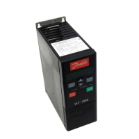
5.3 General Technical Data
Supply voltage VLT 2803-2840 220-240 V (N, L1) 1 x 220/230/240 V ±10%
Supply voltage VLT 2803-2840 200-240 V 3 x 200/208/220/230/240 V ±10%
Supply voltage VLT 2805-2882 380-480 V 3 x 380/400/415/440/480 V ±10%
Supply voltage VLT 2805-2840 (R5) 380/400 V +10%
Supply frequency 50/60 Hz ±3 Hz
Max. imbalance on supply voltage ± 2.0% of rated supply voltage
True power factor (λ) 0.90 nominal at rated load
Displacement power factor (cos φ) near unity (> 0.98)
Number of connections at supply input L1, L2, L3 2 times/min.
Max. short-circuit value 100,000 A
See chapter 5.1 Special Conditions for further information.
Output data (U, V, W)
Output voltage 0-100% of supply voltage
Output frequency 0.2-132 Hz, 1-590 Hz
Rated motor voltage, 200-240 V units 200/208/220/230/240 V
Rated motor voltage, 380-480 V units 380/400/415/440/460/480 V
Rated motor frequency 50/60 Hz
Switching on output Unlimited
Ramp times 0.02-3600 s
Torque characteristics
Starting torque (parameter 101 Torque characteristic=Constant torque) 160% in 1 min.
1)
Starting torque (parameter 101 Torque characteristics=Variable torque) 160% in 1 min.
1)
Starting torque (parameter 119 High starting torque ) 180% for 0.5 s
Overload torque (parameter 101 Torque characteristic=Constant torque) 160%
1)
Overload torque (parameter 101 Torque characteristic=Variable torque) 160%
1)
Percentage relates to frequency converter's nominal current.
1) VLT 2822 PD2/2840 PD2 1x220 V only 110% in 1 min
Control card, digital inputs
Number of programmable digital inputs 5
Terminal number 18, 19, 27, 29, 33
Voltage level 0-24 V DC (PNP positive logic)
Voltage level, logic '0' < 5 V DC
Voltage level, logic '1' > 10 V DC
Maximum voltage on input 28 V DC
Input resistance, R
i
(terminals 18, 19, 27, 29)
approx. 4 kΩ
Input resistance, R
i
(terminal 33)
approx. 2 kΩ
All digital inputs are galvanically isolated from the supply voltage (PELV) and other high-voltage terminals. See
chapter 5.1.1 Galvanic Isolation (PELV) for further information.
All about VLT 2800 Design Guide
MG27E402 Danfoss A/S © Rev. May/2014 All rights reserved. 141
5 5
 Loading...


