4.2 Load and Motor
4.2.1 Configuration
Selection of configuration and torque characteristics has an
effect on which parameters can be seen in the display. If
[0] Open loop is selected, all parameters relating to PID
regulation is filtered out. This means that the user only
sees the parameters that are relevant for a given
application.
100 Configuration
Value:
Speed control, open loop
(SPEED OPEN LOOP) [0]
Speed control, closed loop
(SPEED CLOSED LOOP) [1]
Process control, closed loop
(PROCESS CLOSED LOOP) [3]
Function:
This parameter is used to select the configuration to which
the frequency converter is to be adapted. This makes
adaptation to a given application simple, since the
parameters not used in a given configuration are hidden
(not active).
Description of choice:
If [0] Speed control, open loop is selected, normal speed
control is obtained (without feedback signal) with
automatic load and slip compensation to ensure a
constant speed at varying loads. Compensations are active,
but may be disabled in parameter 134 Load compensation
and parameter 136 Slip compensation as required.
If [1] Speed control, closed loop is selected, better speed
accuracy is obtained. Add feedback signal, and set the PID
regulator in parameter group 400 Special functions.
If [3] Process control, closed loop is selected, the internal
process regulator is activated to enable precise control of a
process in relation to a given process signal. The process
signal can be set to the relevant process unit or as a
percentage. Add feedback signal from the process and set
the process regulator in parameter group 400 Special
functions. Process closed loop is not active if a DeviceNet
card is mounted and Instance 20/70 or 21/71 is selected in
parameter 904 Instance types.
101
Torque characteristic
Value:
Constant torque
(Constant torque) [1]
Variable torque low
(torque: low) [2]
Variable torque medium
(torque: med) [3]
Variable torque high
(torque: high) [4]
Variable torque low with CT start
(VT LOW CT START) [5]
Variable torque medium with CT start
(VT MED CT START) [6]
Variable torque high with CT start
(VT HIGH CT START) [7]
Special motor mode
(Special motor mode) [8]
CT = Constant torque
Function:
Use this parameter to adapt the U/f ratio of the frequency
converter to the torque characteristic of the load. See
parameter 135 U/f ratio.
Description of choice:
If [1] Constant torque is selected, a load-dependent U/f
characteristic is obtained, in which output voltage and
output frequency are increased at increasing loads to
maintain constant magnetisation of the motor.
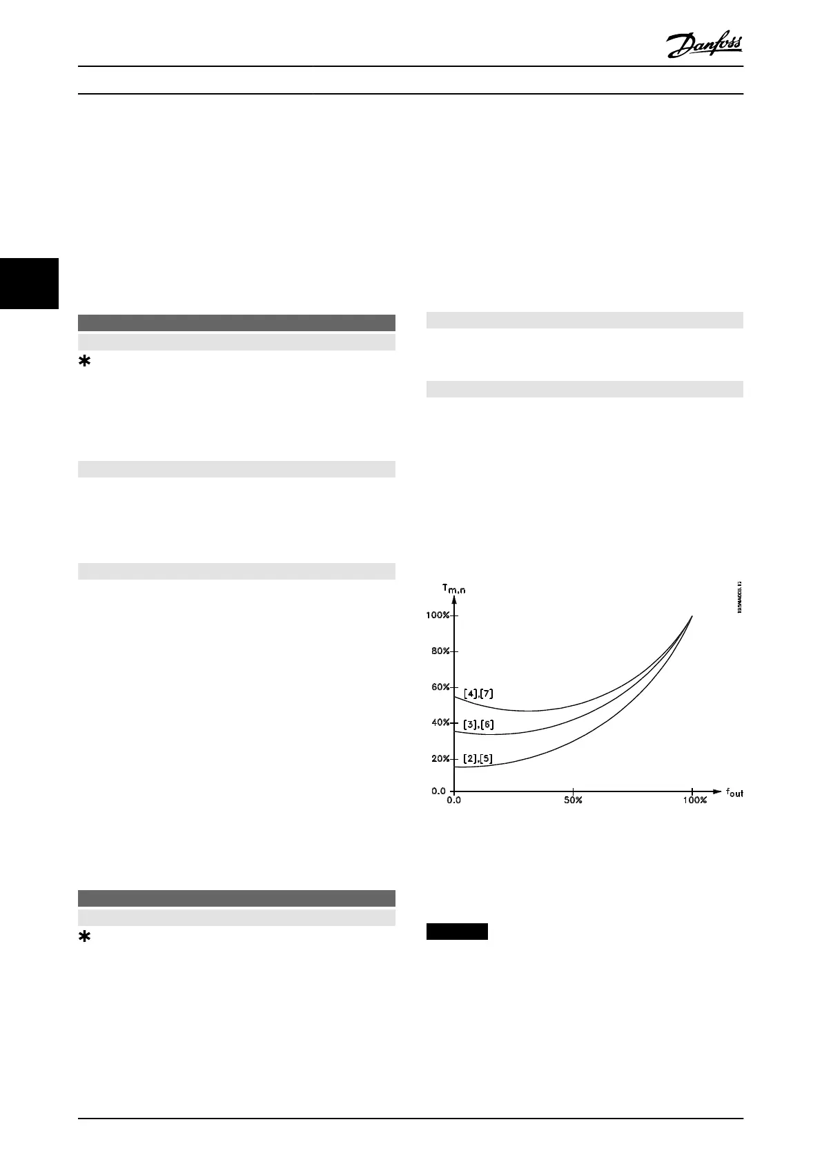
Select [2] Variable torque low , [3] Variable torque medium or
[4] Variable torque high, if the load is square (centrifugal
pumps, fans).
Select [5] Variable torque - low with CT start , [6] Variable
torque - medium with CT start or [7] Variable torque - high
with CT start if a greater breakaway torque is needed than
can be achieved with the 3 first characteristics.
Illustration 4.2 Torque Characteristics
Select [8] Special motor mode if a special U/f setting is
needed that is to be adapted to the present motor. The
break points are set in parameters 423-428 Voltage/
frequency.
NOTICE
Load and slip compensation are not active if variable
torque or special motor mode have been selected.
Programming Design Guide
68 Danfoss A/S © Rev. May/2014 All rights reserved. MG27E402
44
 Loading...


